Summary of Arduino ATmega328 – Hardcore using arduino
This article outlines constructing a custom PCB based on the Arduino Uno design using an ATmega328 microcontroller kit. It details the necessary components for the board, including the chip with a bootloader, crystals, voltage regulators, and capacitors. The guide explains programming the processor via a TTL serial connection using an FT232RL breakout board, highlighting the addition of a 0.1uF capacitor to enable auto-reset functionality similar to standard UNO boards.
Parts used in the Custom Arduino ATmega328 Board:
- ATMega328 microcontroller with Arduino Bootloader
- 8MHz or 16MHz Crystal oscillator
- Capacitors (including 47uF and 0.1uF)
- 3.3V or 5V Voltage Regulator
- PCB mount reset switch
- 10K pullup resistor
- LED and resistor
- FT232RL USB to Serial breakout board
- White, Yellow, and Green wires
Ok, you’ve completed your prototype using an Arduino Uno board, perhaps using a shield or a breadboard for any additional components, but now you want to finalise your design and construct it using your own pcb. Well, that is fairly straightforward, as we have made a complete kit of essential parts available for the ATMega328 micro (click here). The kit includes the following items (depending on which bootloader chip 16MHz or 8MHz)
- ATMega328 complete with Arduino Bootloader already installed
- 8 or 16MHz Crystal and capacitors
- 3.3V or 5V Voltage Regulator and 47uF capacitor
- PCB mount reset switch and 10K pullup resistor
- 0.1uF capacitor for self-reset
- LED and resistor
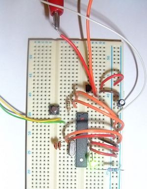
The kit includes the essential items to create your own Arduino 328 board. Here is a breadboard with all the components mounted and running the demo led flash program
The White, Yellow and Green wires are connected to a serial TTL connection for programming the microcontroller (see below)
And below is the schematic for this circuit.
You can program the processor directly from the Arduino IDE. All you need is a TTL serial connection. The FT232RL USB to Serial breakout board is ideal for this. Now that we are using the modified Arduino UNO bootloader, we have also included a 0.1uF capacitor in the kit which allows for the auto-reset functionality of the UNO boards. This capacitor goes between the DTR pin on the FT232RL USB to Serial board and the Reset pin on the ATmega328.
Just connect th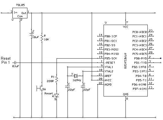 e ATMega328 RX (pin 2) to TX on the breakout board, the ATMega328 TX (pin 3) to RX on the breakout board, connect the 0V and you are connected
For more detail: Arduino ATmega328 – Hardcore
- How do I program the ATmega328 processor?
You can program the processor directly from the Arduino IDE using a TTL serial connection. - What is the ideal tool for creating a TTL serial connection?
The FT232RL USB to Serial breakout board is ideal for this purpose. - Why is a 0.1uF capacitor included in the kit?
This capacitor allows for the auto-reset functionality found on UNO boards by connecting the DTR pin to the Reset pin. - Which pins connect between the microcontroller and the breakout board?
Connect the ATMega328 RX (pin 2) to TX on the breakout board and the ATMega328 TX (pin 3) to RX on the breakout board. - What bootloaders are available for the ATMega328 in this kit?
The kit includes chips with either a 16MHz or 8MHz bootloader installed. - Can I use a breadboard to test the components before building the PCB?
Yes, the article shows a breadboard setup where all components are mounted and running a demo LED flash program. - What voltage regulator options does the kit support?
The kit includes a 3.3V or 5V Voltage Regulator depending on your needs. - How do I ensure the board resets automatically during programming?
By placing the 0.1uF capacitor between the DTR pin on the FT232RL board and the Reset pin on the ATmega328.