Summary of Yun Shield – Toggle an LED using Arduino Uno with Proteus Simulation
This project demonstrates remote LED toggling using an Arduino Uno with a Yun Shield, controlled from a mobile device and testable in Proteus. Pin 13 is configured as output; a mobile IoT button triggers the Yun Shield to send commands to the Arduino, which toggles the LED state. The design uses event-driven logic, a setup/idle/trigger workflow, and visual programming for beginner-friendly IoT learning and prototyping.
Parts used in the Yun Shield – Toggle an LED using Arduino Uno with Proteus Simulation:
- Arduino Uno
- Yun Shield
- LED
- Resistors
- Power supply (+5V)
- Proteus simulation environment
Introduction
This microcontroller project demonstrates how to toggle an LED using an Arduino Uno and a Yun Shield, controlled from a mobile device. It is a simple but powerful introduction to Internet of Things (IoT) concepts using Proteus simulation and visual programming.
The project shows how physical hardware like an LED can be controlled remotely, making it ideal for beginners exploring embedded systems, DIY electronics, and IoT-based control systems.
By combining Arduino, IoTBuilder logic, and a clear workflow, this project delivers a clean learning experience without unnecessary complexity.
This Arduino IoT LED control example is ideal for beginners learning IoT-based embedded systems and mobile-controlled electronics.

How the Project Works (Overview)
The system uses an Arduino Uno connected to a Yun Shield, which acts as a bridge between a mobile device and the microcontroller.
An LED is connected to digital pin 13 of the Arduino. When a button is triggered from the mobile application, the Yun Shield sends a command to the Arduino.
The Arduino toggles the LED state (ON or OFF) based on the received trigger. The logic continuously updates the LED state, making real-time remote control possible.
Block Diagram / Workflow Explanation
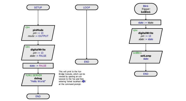
The workflow of the project follows three main stages:
-
Setup Phase
-
Arduino pin 13 is configured as an OUTPUT.
-
The LED is initially turned OFF.
-
A debug message (“Hello World”) is sent to the Yun server for verification.
-
-
Idle Loop
-
The loop remains empty, waiting for external IoT triggers.
-
-
IoT Trigger Action
-
A mobile button (
IotBtn1) triggers the event. -
The LED state is toggled.
-
Arduino updates pin 13 accordingly.
-
The new LED state is reflected both physically and on the IoT interface.
-
This clean separation between setup, idle, and trigger-based execution makes the system easy to understand and modify.
Key Features
-
Remote LED control using a mobile device
-
Arduino Uno and Yun Shield integration
-
IoT-based trigger system
-
Real-time LED state toggling
-
Simple digital output control
-
Designed using Visual Designer for Arduino AVR
-
Fully testable in Proteus simulation
Components Used
-
Arduino Uno
-
Yun Shield
-
LED
-
Resistors
-
Power supply (+5V)
-
Proteus simulation environment
Applications
-
Smart home lighting control
-
IoT learning and training projects
-
Remote device control demonstrations
-
Embedded systems education
-
DIY electronics and prototyping
-
Mobile-controlled automation systems
Explanation of Code (High-Level)
The firmware initializes digital pin 13 as an output to control the LED.
During setup, the LED is turned OFF, and a debug message is sent to confirm communication with the Yun server.
The main loop remains idle, relying entirely on IoT events.
When the mobile button trigger is received, the system toggles a Boolean state variable and updates the LED accordingly using digitalWrite.
This event-driven structure is efficient and well-suited for IoT applications.

Flowchart
Proteus Simulation
In the Proteus simulation, the Arduino Uno is connected to the Yun Shield module and an LED on pin 13.
When the IoT trigger is activated, the LED toggles between ON and OFF states instantly.
The simulation accurately reflects real hardware behavior, allowing testing and validation before physical deployment.
FAQs
[ultimate-faqs Include_category=”yun-shield-toggle-an-led”]- How does the mobile device control the LED?
The mobile button sends a trigger to the Yun Shield, which forwards a command to the Arduino to toggle the LED. - Which Arduino pin is used for the LED?
The LED is connected to digital pin 13 of the Arduino. - What is the role of the Yun Shield?
The Yun Shield acts as a bridge between the mobile device and the Arduino, relaying IoT triggers. - Does the main loop run continuous logic?
No, the main loop remains idle and relies on IoT events to trigger actions. - How is the LED state toggled?
The Arduino toggles a Boolean state variable upon receiving the trigger and updates pin 13 with digitalWrite. - Is the project testable without physical hardware?
Yes, the project is fully testable in the Proteus simulation environment. - What is sent to verify Yun server communication?
A debug message Hello World is sent to the Yun server during setup for verification. - What are typical applications of this project?
Applications include smart home lighting control, IoT training, remote device demos, and embedded systems education.