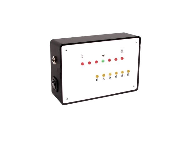
Build your own electric guitar tuner using the Arduino! I decided to make this because I wanted to experiment with audio input and frequency detection. I used Amanda Ghassaei’s method for Arduino Frequency Detection in order to get frequency readings using the Arduino. I used LEDs that light up according to the frequency of the audio input, indicating whether the string being played is sharp, flat, or in tune. This works like any other guitar tuner, but you can make it yourself!
Step 1: What you need
(x1) Arduino Uno (RadioShack #276-128)
(x1) TL082 Dual JFET Input Op Amp (RadioShack #276-1715)
(x1) 6x4x2″ project enclosure (RadioShack #270-1806)
(x6) 5mm Yellow LED (RadioShack #276-021)
(x6) 5mm Red LED (RadioShack #276-041)
(x1) 5mm Green LED (RadioShack #276-022)
(x13) 150 Ohm Resistor (RadioShack #271-1109)
(x2) 9V Battery (RadioShack #23-1134)
(x2) 9V Snap Connector (RadioShack #270-324)
(x1) M-type power plug (RadioShack #274-1569)
(x1) SPST Rocker Switch (RadioShack #275-693)
(x1) 1/4″ Mono Audio Jack (RadioShack #274-255)
(x1) Matching Printed Circuit Board (RadioShack #276-170)
(x1) Grid-Style Printed Circuit Board (RadioShack #276-149)
(x3) 100kOhm Resistor (RadioShack #271-1347)
(x1) 22kOhm Resistor (RadioShack #271-1339)
(x1) 10uF Capacitor (RadioShack #272-1025)
(x1) 100nF Capacitor
(x1) 6x4x.125″ Acrylic Sheet
Step 2: Drill
Drill a starter hole on the side of your enclosure using a 1/8″ drill bit. Drill into the starter hole using a 13/16″ spade bit to create a larger hole for the SPST rocker switch. The rocker switch will serve as an on/off switch for the tuner.
Drill a hole beneath the on/off switch hole using a 23/64″ bit. This hole is for your audio jack.
Step 3: On/Off Switch
Solder the red end of one of your battery snaps to one of the lugs on the switch and solder a red wire to the other lug of the switch.
Feed the snap and wire through the 13/16″ hole in your enclosure and fasten it in place with its mounting nut.
Step 4: Audio Jack
Solder a green wire to the output terminal and a black wire to the ground terminal on the audio jack.
Insert the audio jack in the 23/64″ hole you drilled and fasten it in place with its mounting nut and washer.
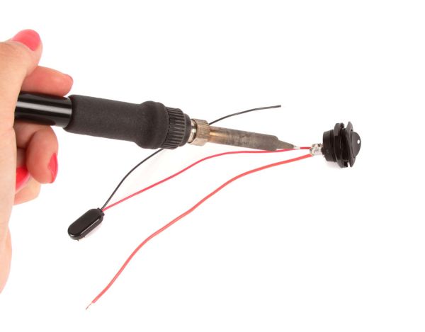
Step 5: Power Plug
Take apart the M-type power plug.
Solder a red wire to the plug’s tip terminal, and a black wire to the plug’s barrel terminal.
Thread both wires through the black casing and screw the casing back onto the plug.
Step 6: Amplify and Offset
The audio signal coming from the electric guitar needs to be amplified to be about 5V peak to peak and and offset to be centered around 2.5V as opposed to 0V. The signal needs to be between 0 and 5V in order for it to be read by the Arduino’s analog pin. It should also have the greatest amplitude possible without clipping in order to get more accurate frequency calculations.
Above is a schematic of the circuit you will need to do this.
I recommend building this circuit on a breadboard and testing it out using an oscilloscope before soldering it together. Your audio input should be the green wire of the audio jack. Connect the black wire of the jack to ground. Attach your scope probe to the output of the DC offset (where the circuit is attached to A0 on the Arduino). Turn the volume on your guitar all the way up and plug your guitar into the audio jack. Play every string and check on the oscilloscope to make sure your signal is centered around 2.5V and that the signal is close to but does not exceed 5V peak to peak.
Try running this modified version of Amanda’s code for Arduino Frequency Detection to test out the Arduino’s frequency calculation. The only thing I have changed from her code is I removed the clipping indicator LED and instead printed “clipping” in the serial monitor whenever the signal clips.
The serial monitor should print the frequency of the strings being played. The guitar’s strings should have the following frequencies:
E – 82.4 Hz
A – 110 Hz
D – 146.8 Hz
G – 196 Hz
B – 246.9 Hz
E – 329.6 Hz
Since the the higher strings have a much lower amplitude signal than the lower strings, it can be tricky to get the frequency detection to work. Amanda’s code has a variable called ampThreshold that is the minimum signal amplitude for the Arduino to calculate frequency. For the guitar tuner, the ampThreshold should be high enough that the Arduino calculates the frequency of the higher strings, but also low enough that it does not pick up too much noise from the lower strings. I found that an ampThreshold of 20 works. You have to strum the high strings a bit harder to get the Arduino to pick them up, but the frequency detection works well. You can experiment with other values to get it to work for you. Values ranging from 10 to 30 work okay. For more information on Amanda’s algorithm for frequency detection, check out her Instructable: Arduino Frequency Detection.
Step 7: Solder the chip
Solder the TL082 to the grid-style PC board.
For mor detail: Arduino Guitar Tuner