Summary of Arduino Compatible apc220 Wireless rf Module with Graphics LCD
This project builds a 16-node Arduino-compatible wireless mesh using APC220 RF modules and ILI9341 graphics LCDs. Nodes sample two analog inputs, can output two analog values or control relays, link any node to any other, and display data locally as text or graphics. The mesh is fault-tolerant, synchronised by a shared clock with time-slot transmission, supports up to 1000 m range between nodes, and routes messages via multiple paths. PCB Eagle files and Arduino code (with Bodmer display libraries and selectable fonts) are provided.
Parts used in the 16 node mesh with graphics LCD:
- Arduino UNO clone
- ILI9341 graphics LCD
- APC220 wireless RF module
- Custom PCB (Eagle layout)
- Resistors for 5V to 3.3V level shifting
- Capacitors for analog input smoothing (optional)
- External power supply (7V to Vin)
- Relay modules (optional, controlled by spare Arduino pins)
- Wires, headers, and sundry components
 16 node mesh, up to 1000m between nodes, sample two analog voltages per node, link any node to any other node, display data on any node with either graphics or text display, turn on relays based on data at any node, fault tolerant with data going via multiple paths.
Arduino Compatible apc220 Wireless rf Module with Graphics LCD:
Step 1: Wireless mesh with graphics LCD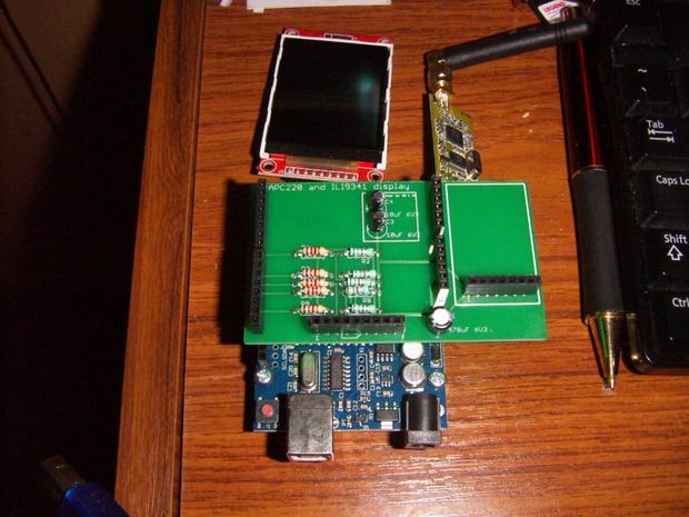
This Instructable merges two existing Instructables – one using 20×4 text displays http://www.instructables.com/id/Simple-Arduino-Wir… and some great work by Bodmer on graphics and text modes for the ILI9341 http://www.instructables.com/id/Arduino-serial-UAR…
A wireless mesh exchanges information between all nodes, with a common clock that is also exchanged, so that all nodes are synchronised and each node transmits in its own time slot. The mesh is tolerant of faults, including nodes not functioning, and messages will find their way around the network via multiple paths. This network keeps things simple – each node can sense two analog values, and output two analog values. Outputs can be linked to any input from another node.
Parts are an Arduino UNO clone ($5), ILI9341 display ($5), APC220 ($20) PCB ($3) and sundry components. The APC220 module is expensive compared to other wireless options, but it has a long range (1000m) and is reliable through walls and trees.
Step 2: Schematic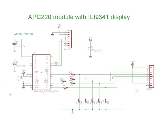
Resistors are needed to drop the voltage from 5V to 3.3V. Analog inputs A0 and A1 have optional capacitors to smooth any inputs that might come in on long leads, such as a temperature sensor. The board is powered from an external supply – 7V on Vin minimises heat losses but ensures that the 5V is stable on the Arduino. Library parts for the Arduino layout are available from Sparkfun.
Step 3: PCB layout
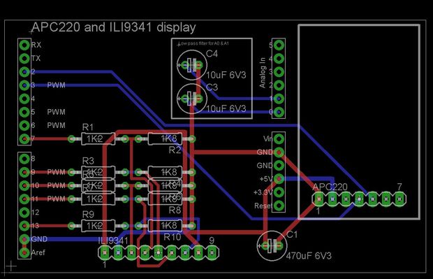
PCB layout is shown for Eagle. This board is small enough that it can be made with the free version of Eagle. I get boards made by Seeed Studios https://www.seeedstudio.com/service/index.php?r=pcb The autorouter on eagle works fine for laying out the board.
Step 4: Text display
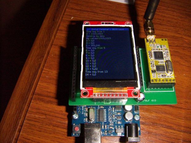
With a change to one line of code it is possible to either display the text the mesh is using to talk amongst itself, or to display a value from any node as a graphical display. Having both options does fill the arduino memory to 98% (with about half of that as fonts), but it makes it easier to work with the code as only one program is needed.
Step 5: Arduino code
Program is attached. See Bodmer’s instructables (search Instructables Bodmer on Google) for the display driver and font files.
This line of code changes between text and graphic mode
boolean displayMeter = true; // false displays text from the mesh, true displays just the meter
There are also a node number which needs to be 0 to 15 for each node in the mesh.
There is also a font include file that determines which fonts are loaded – this is in the package from Bodmer’s instructable, and to fit in the memory only font 2 and font 4 are used. Please contact me in the comments section if you are having trouble fitting it all into the UNO as it is likely the fonts are the problem.
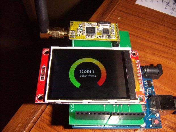
For the solar watt display on the first page, this uses a kilowatt meter with a pulse output, and an arduino to measure the time between pulses and convert to an analog voltage, which is then fed into the mesh.
There are enough spare pins on the Arudino to turn on a couple of relays and control things based on values that might be measured many kilometers away
- How many nodes does the mesh support?
The described setup supports 16 nodes with node numbers 0 to 15. - What wireless module provides the range up to 1000m?
The APC220 wireless RF module provides long range up to 1000 m. - Can any node display data from any other node?
Yes, any node can display data from any other node as text or graphics. - How many analog inputs does each node sample?
Each node samples two analog voltages (A0 and A1). - Can nodes control relays based on remote data?
Yes, spare Arduino pins can be used to turn on relays based on values from remote nodes. - Is the mesh fault tolerant if nodes fail?
Yes, the mesh is fault tolerant and messages can route via multiple paths around failures. - How are nodes kept synchronized?
Nodes share a common clock and each node transmits in its own time slot for synchronization. - What display modes are available on the node?
Nodes can display either mesh text or a graphical meter by changing one line of code. - What voltage should the external power supply provide?
The board is powered from an external supply; 7V on Vin is recommended. - Where do the display fonts and driver come from?
The ILI9341 driver and font files are from Bodmer's instructable and are included in the package.