Background
In this blogpost we’re going to deal with the Compass Module 3-Axis HMC5883L from Parallax and how to integrate it into an Arduino.
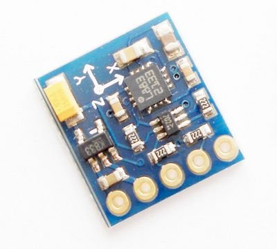
The Compass Module 3-Axis HMC5883L is designed for low-field magnetic sensing with a digital interface. This compact sensor fits into small projects such as UAVs and robot navigation systems.
The sensor converts any magnetic field to a differential voltage output on 3 axes. This voltage shift is the raw digital output value, which can then be used to calculate headings or sense magnetic fields coming from different directions. Example code in PBASIC, Spin, and C are provided in the downloads.
Features:
- Measures Earth’s magnetic fields
- 3-axis magnetoresistive sensor
- Wide magnetic field range (+/-8 gauss)
- 1 to 2 degree compass heading accuracy
- Precision in-axis sensitivity and linearity
- I2C digital Interface
- Fast 160 Hz maximum output rate
- Designed for use with a large variety of microcontrollers with different voltage requirements
Application Notes:
- Auto and personal navigation
- UAV systems
- Robotic navigation
- Location-based services (LBS)
Key Specifications:
- Power Requirements: 2.7 to 6.5 VDC
- Communication Interface: I2C (up to 400 kHz)
- Operating temperature: -22 to +185 °F (-30 to +85 °C)
- Dimensions: 0.725 x 0.650 in (1.8 x 1.7 cm)
What It Can Do
- Measures the earth’s magnetic field in three axes, with a 1–2 degree accuracy
- Provides individual readings for each axis, which may be used separately or together for 3D calculations
- Measures raw strength (gauss) of a nearby magnetic source
The 3-Axis Compass module measures magnetic fields in three directions – or axes, labeled X, Y, and Z. In its most simple form, the module can be used as a basic compass to find earth’s magnetic north.
The compass module can also sense the relative strength of a nearby magnetic source, such as those caused by magnets or electric fields. As the sensor detects magnetism in three dimensions, it can determine relative distance and direction to these sources.
Compasses are commonly uses with accelerometers, where the data from both the compass and accelerometer can provide extended information.
One application of adding an accelerometer is to compensate for any tilt of the compass. As with most any compass, the reading is affected if the compass is not level.
Hardware Required
- Arduino Board
- (1) Compass Module 3-Axis HMC5883L
- breadboard
- hook-up wire
Circuit
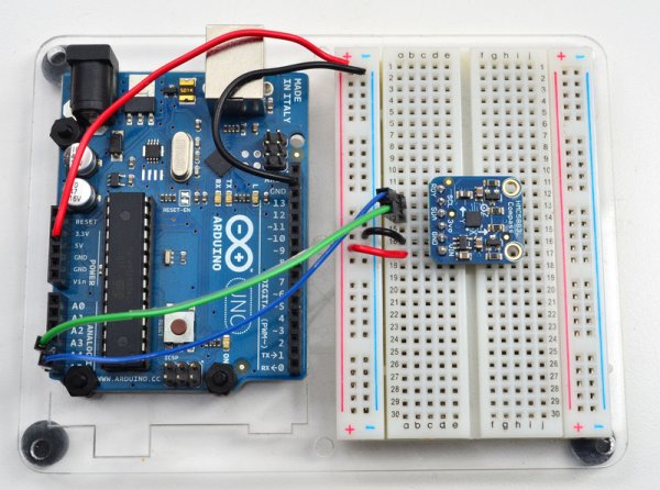
Connect the 5V and GND pins of the compass to the power and ground ports on the Arduino. Connect analog pin 4 of the Arduino to the SDA (Data) out pin of the compass, and analog pin 5 to the SCL (Clock) out pin.
The picture below shows you essentially how the circuit should be laid out.
Don’t forget that your Arduino must be connected to your computer in order for it to transmit serial data and don’t forget to set the Baud Rate of your serial connection to be 9600.
The Code
1 2 3 4 5 6 7 8 9 10 11 12 13 14 15 16 17 18 19 20 21 22 23 24 25 26 27 28 29 30 31 32 33 34 35 36 37 38 39 40 41 42 43 44 45 46 47 48 49 50 51 52 53 54 55 56 | |
At the end of uploading and running the code listed above you will start to see some serial output like in the image below.
Here’s a picture of the actual circuit built.
Source Code
In a follow up blog post I’ll discuss how you can use both the Compass Module 3-Axis HMC5883L in conjunction with the Memsic 2125 Dual-axis Accelerometer to compensate for any tilt of the compass.
Posted by Tony Guntharp Arduino, Compass Module 3-Axis HMC5883L, Open Source
For more detail: Arduino + Compass Module 3-Axis HMC5883L