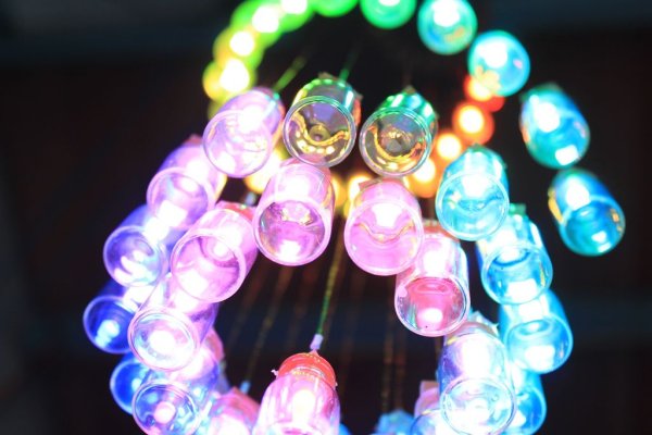
E-Edit: Thank you very very much for voting for me in Featured Author, Glue and Battery Powered Contests! Cheer up and wait for my project so special is coming…
Edit:
If you really like this project, you can vote for me on the top right corner, forFeatured Author Contest , just three days after the contest closes. And don’t forget the other 2 contests: Glue and Battery Powered. Thank you very much in advance!!!
Hi All,
This is my second instructable: Arduino chandelier from mini jars. My first one was my : Cuckoo Alarm Clock from Hard Drive.
I wanted to give my room some special design, with mooth lighting so when I had the option to use RGB leds and a Arduino board I decided I needed my own making a chandelier.
Step 1: Intro: Gallery
Before we get started we are going to need a little bit of motivation, take a look at these pictures and realize what you will be making.
This project very tedious and time consuming. Any time that you get frustrated while making this project, take a deep breath, come back to this step, take a look at the pictures and remember what you are working towards!
Step 2: Materials List
Here is what you need to make your chandelier:
Electronics:
- PCB sheet
- Arduino mini 5V
- USB Serial Light Adapter or Arduino Uno, Duemillanove or something similar to act as a HOST (detachable Chip!!)
- RGB Leds (50 pcs)
- 8-bit shift register 74hc595d SMD (19 pcs)
- Octal Bus Transceiver 74hc245d SMD
- Electrolytic Decoupling Capacitors – 100uF/16V
- High capacity rechargeable battery
Frame:
- Acrylic sheet
- Spray paint
- Copper wire
- Insulation Sleeving
- Mini jars (50 pcs)
Tools:
- Handsaw
- Drill
- Drill bits
- Hot glue and it’s gun
- Super glue
- Soldering iron
- Solder
- Wire cutters
- Pliers
- …
Step 3: Preparing the acrylic frame
I decided the dimensions of my acrylic frame at 6.5″ diameter, it fits my room, not too small and easy lighting throughout the room. 6.5″ with 50 jars and 50 leds corresponding.
First, drawing circles on acrylic plate, divide the LED position that you want to sort, then use a handsaw or sawmill parasols for sawing acrylic sheet. Next, drill holes at the locations specified by 2mm drill bit.
I broke the an acrylic plate because I saw too fast, of course, the experience for you as sawing slowly.
Next, remove the protective paper sheet from the acrylic and installation of insulation sleeving pipe was cut short into boreholes.
Finally, using spray paint to decorate it.
Step 4: Circuit Diagram and Programming
After shopping all the electronic parts, I assemble circuit follow the circuit diagram reference from elcojacobs.
With 50 RGB leds, I need 19 pcs of 74hc595 to driven.
Explain:
Take a look at the schematic
Each RGB led consists of three colors, corresponding to 3 pins controller.
Each 8-bit shift register 74HC595 has 8 control output.
I need to control 50 RGB Leds, which means I need 50×3 = 150 pins control, corresponding to 150/8 = 19 shift registers.
HOW TO UPLOAD THOSE SKETCHES TO AN ARDUINO MINI:
I’ve been into Arduino programming lately and looking forward to create a small form factor project. To get code into it you might want to try the following technique.
You’ll need an USB Serial Light Adapter or Arduino Uno, Duemillanove or something similar to act as a HOST (detachable Chip!!) .
Basically, connect the main Arduino’s 5v, GND, RX,TX (not crossed, just RX to RX and TX to TX) and RESET to the mini. Now for the most important part. DETACH the ATMega chip from the host board (Duemilanove, Uno.. what ever) and start uploading your sketches as you would with the normal arduino. No need to change the Board in the Arudino software. THAT’s IT. Nothing more. Just do it and enjoy.
About Programming:
I using ShiftPWM library for Arduino, you can download at Elcojacops Githup. Very thankful to Elco Jacobs for this library. You can refer to the example file in this library.
Based on software PWM on site http://www.elcojacobs.com/shiftpwm/ I chose the PWM frequency is 60, the maximum brightness is 255.
My code file is attached below.
Step 5: Making printed circuit and soldering
How to make print circuits boards?????
Just type and search, hundreds of results on Instructables.
Refer to the Eagle pcb file is attached below, including control board and Leds board.
Note: PCB file has not been finalized.
Step 6: LEDs soldering
Sawing Led board up into small pieces, then soldering the RGB Leds on it.
Finally, use pliers to cut short the pins for the leds
For more detail: Arduino Chandelier from Jars


