Summary of Bedazzler: DIY non-lethal weaponry using arduino
This article details a DIY open-source project to build "The Bedazzler," a handheld LED incapacitator inspired by a US Homeland Security device. For under $250, builders can create a non-lethal weapon using 36-37 high-wattage LEDs, an Arduino microcontroller, and MOSFETs. The project includes source code and schematics, warning users of potential side effects like nausea and dizziness. It emphasizes that this is not a kit but a guideline for makers to assemble and modify the design themselves.
Parts used in The Bedazzler:
- 36 or 37 1+ Watt LEDs (Red, Green, Blue)
- Narrow-beam lenses (approx. 20mm diameter, 5-6 degrees)
- Balancing resistors (1.0 ohm 1210)
- Choke resistor (0.5 ohm at 5W)
- LED plate (6-inch diameter, FR4 with copper fill or aluminum core)
- 16 or 18 gauge wire
- 6 N Channel logic level power MOSFETs
- Arduino or AVR microcontroller (e.g., ATmegax8 series)
- Battery capable of sourcing 4A at 4V+ (e.g., SLA or D cells)
- Heatsink and fan
- 9V battery + holder with switch
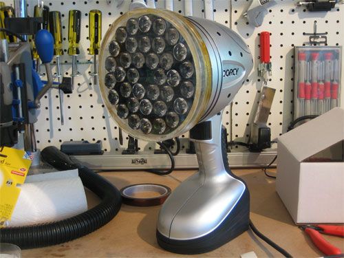
- Enclosure (repurposed flashlight housing)
- ATX power supply for testing
Our first open source Homeland Security non-lethal weapon project – The “THE BEDAZZLER: A Do-it-yourself Handheld LED-Incapacitator”.
After attending a conference where the $1 million “sea-sick flashlight” (named “THE DAZZLER”) was demonstrated by the US Dept. of Homeland Security, we decided to create our own version. For under $250, you can build your own dazzler and we’ve released the source code, schematics and PCB files to make it easy. A great Arduino project for people who really like blinking LEDs. We also added in a mode selection so you can put it into some pretty color-swirl modes, great for raves and parties!
Yes this project does indeed cause: Nausea, dizziness, headache, flashblindness, eye pain and (occasional?) vomiting! So don’t use it on your friends or pets.
Please note: This is not a kit, nor for sale…so don’t ask us. All documentation is on the design and download pages.
Mad props to Scott Johnston for LED assistance. Sk0t r0x!
Step 1: Introduction
Parts list
To make this project you’ll need:
- 36 or 37 1+ Watt LEDs. there are 2 Watt LEDs that are now easily available. For color versatility you can use 12 each of red green and blue. Or you can go with 18 each of green/blue for more effective dazzling. These range around $3 each. Look on eBay or other closeouts to get slightly-older LEDs for less. We used some older Cree XLamp XR-E 7090
- You’ll also need lenses/optics for each LED. Go with narrow-beam lenses, about 20mm diameter. 6 or 5 degree will be most effective. (Like this, but make sure you get ones that match your LED)
- Balancing resistors, one for each LED. I used 1.0 ohm 1210’s
- For red LEDs (and maybe green/blue depending on your power supply) you may need a choke resistor 0.5 ohm at 5W may be OK. The internal resistance of the battery and Rds of the FET will make a difference, so do math and measurements!
- 6″ diameter LED plate, see the downloads page for layout. This holes the LEDs and lenses. In theory a aluminum core LED is helpful but we found that for quick blasting, FR4 with copper fill worked just fine.
- 16 or 18 gauge wire for connecting things up
- 6 N Channel logic level power MOSFETs. We used FDP6030BLs. Nearly anything that can sink 2A is just fine.
- Arduino or other microcontroller. The AVR atmegax8 series such as found in the arduino is handy because it has 6 hardware PWMs. We used a DC boarduino and attached an FTDI cable to upload the firmware
- Battery capable of sourcing 4A at 4V+. 3 D cells or a lead acid is a good choice. We used a 4A 6V SLA that came with the lantern
- Heatsink. A spare AMD processor heatsink and fan worked nicely and was free!
- 9V battery + holder with switch for the arduino, seperate supplies prevent noise issues when driving such large loads
- Enclosure. We repurposed a cheap yet enormous flashlight from Sears. It was pricey at $40 but had the benefit of including a lead acid battery (which would have run almost $20 with shipping) and a basic lead acid charger.
- Power supply for testing, a ATX power supply is a good way to generate 5A+ at 5V
Step 2: Build it: The PCB
You’ll want to start by getting an LED plate fabbed at your favorite PCB manufacturer and acquiring all the materials necessary (image 2a).
Start by soldering in one color of LEDs (in the photo there are a few LEDs soldered in from other strings. Go with green to start. (image 2b)
You’ll want a nice powerful soldering iron, use leaded solder since its hard enough to solder to the copper plane! (image 2c)
Use 1 ohm (or so) 1210’s for the balancing resistors (image 2d)
For testing you’ll want a benchtop supply, or use an ATX power supply with a jumper between the green power line and ground (image 2e)
Test the LEDs to make sure you put them in the right place. Each ‘string’ is 6 LEDs. (image 2f)
Solder in all the green LEDs (image 2g)
Step 3: Build it: The Controller
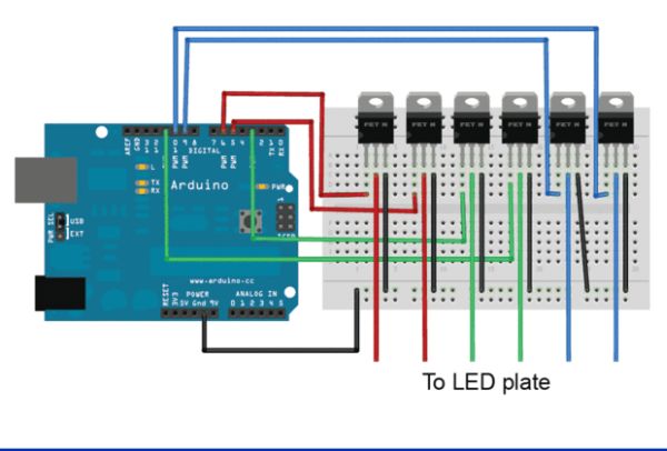
Once you have a single color in place, you’ll want to build the controller. I used a boarduino (Arduino clone) but any microcontroller is fine. Wire up the power FETs so that the gates are connected to the hardware PWM outputs, and the sources to ground. (images 3a & 3b)
To make traces on perfboard high-current-capacity you can use a 20 gauge wire as a backing and solder on top to make a path. (image 3c)
Which you can sort of see here (image 3d)
You don’t have to wire up all the FETs now, start with one. We used 5.08mm (0.2″) terminal blocks to make wiring easy (image 3e)
Step 4: Build it: Testing & The Heatsink
Do lots of testing and be careful to connect power up properly since there are no protection diodes (image 4a)
You can load some PWM testing firmware onto the microcontroller to check the LEDs as you work (image 4b)
Complete soldering in all the LEDs (image 4c)
A final test PWMing through all the LEDs. It heats up fast so keep the max power low and/or dont run it more than half a minute. (image 4d)
Since we were too cheap to get a proper metal PCB, we’ll be attaching a heatsink to the outside. While far from ideal, a spare AMD processor heatsink worked just fine. Remove the fan, take off the metal clip and then reattach the fan. Check the fan to see if it will run off of 9V. Ours did OK (image 4e)
If you have thermal paste, spread some on the heatink. If you didn’t tent the vias, use kapton tappe or similar to prevent them from shorting to the heatsink (image 4f)
For more detail: Bedazzler: DIY non-lethal weaponry
- How much does it cost to build the Bedazzler?
The project can be built for under $250. - What are the health risks associated with using this device?
It can cause nausea, dizziness, headache, flashblindness, eye pain, and occasional vomiting. - Is this project available as a pre-made kit for purchase?
No, this is not a kit nor is it for sale; all documentation is on the design and download pages. - What type of microcontroller is recommended for the controller?
An Arduino or other microcontroller with hardware PWM outputs, such as the AVR atmegax8 series, is recommended. - Can I use different colors of LEDs for the array?
Yes, you can use 12 each of red, green, and blue for color versatility, or 18 each of green/blue for more effective dazzling. - What kind of lens should be used for the LEDs?
You should use narrow-beam lenses about 20mm in diameter, ideally 5 or 6 degrees. - Does the project include a mode selection feature?
Yes, there is a mode selection added to allow for color-swirl modes suitable for raves and parties. - What is suggested for cooling the LED plate since a metal PCB was not used?
A spare AMD processor heatsink and fan attached to the outside of the board is suggested for cooling.