Recently I have been playing around with Arduino.
Arduino is really cool and is a great way to learn electronics.
In this Instructable I will teach you the basics of Arduino including:
- LED’s
- Buttons
- Potentiometers
- Resistors
- Tinkercad
- And a project with this knowledge.
Step 1: The Board
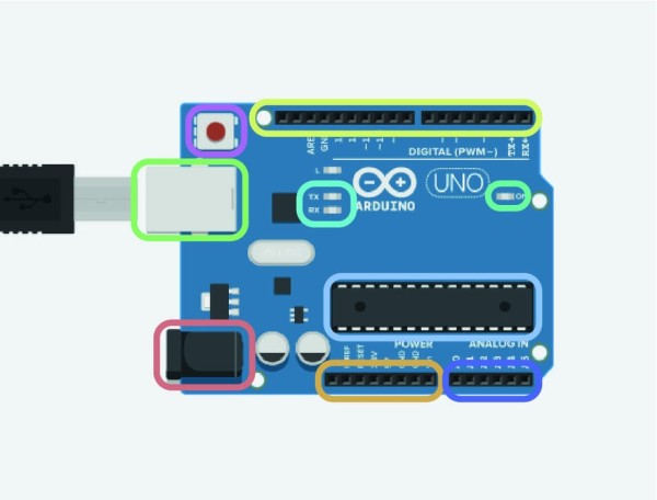
The controller can be broken down into a few simple parts. The colours correspond to the image.
- The green box provides power to the Arduino and this is plugged in to a USB cable.
- The orange provides the power to the bread board either 5v or 3.3v as well as ground.
- The red port is a port to power the Arduino without USB at 7-12v.
- Purple is a reset button for the microcontroller.
- Pale blue is the brains of the operation.
- Yellow are the digital pins.
- Navy is analog in.
- Turquoise is the power LEDs that indicates if there is power.
- Finally cyan is TX and RX LEDs They will flash rapidly when you upload a sketch/code.
You don’t have to remember all the names but its good have a vague idea of what everything is.
Step 2:

A component is anything that is included in a circuit. This could be a light, a motor or potatoes!
Components have different ways of being presented:-
Realistic illustrations are images or drawings of the component that look like the component.
Schematic diagrams use symbols to represent components.
In this section I will run through some of the basic components that will be used in our project at the end.
Step 3: LED
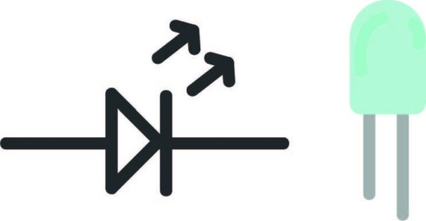
On the left is the schematic diagram and on the right is the realistic illustration.
You will notice that one leg of the LED is longer than the other. The longer leg is called anode and connects to power and the shorter leg is called cathode.
Tip – (The black – is usually ground in circuits and red + is power.)
What is an LED?
An LED is a diode that lights up when electricity passes through it.
LED = Light Emitting Diode
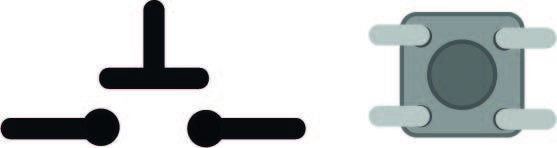
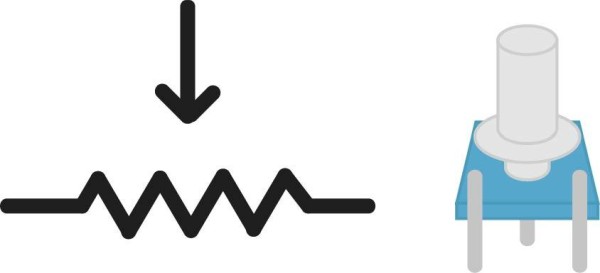
Push buttons are switches that will continue the circuit if pressed. The buttons can also be read in your program, allowing you to start sequences with the push of the button.
How it works?
A push button works by having two pieces of conductive metal apart from each other. In the middle of these there is another sprigged piece of metal that if pushed down will complete the circuit.. This allows electricity to flow through.
How is it detected?
When the electricity flows through you can channel it into digital, in which current can be read.
Step 5: Resistors
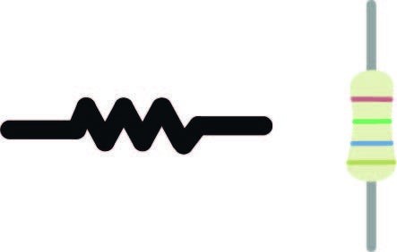
A resistor resists the flow of electricity and decreases the output voltage.
How it works
Electricity is a type of energy. Like all energy, you can turn it into a different type of energy. A resistor works by heating up very slightly therefore converting the electricity into heat (another energy.)
Why we need it.
We need resistors, as not all components will run on the same current as it will simply be too much.
On a resistor there are lots of different colours!
What are these? The colour on a resistor is a code that tells us how much energy they are going to soak up from our circuit.
Here is a Resistor decoder to help you discover this.
Step 6: Potentiometers
A potentiometer is a component that you can twist to angles you can read.
How it works
Inside the potentiometer is a circular disk of metal going between the front two legs. The middle knob is a piece of metal that touches the ring at the point it is facing.
Finally, the third leg reads the resistance between the two legs and the knob.
All of this results in us reading the angle of the knob.
Step 7: Bread Board
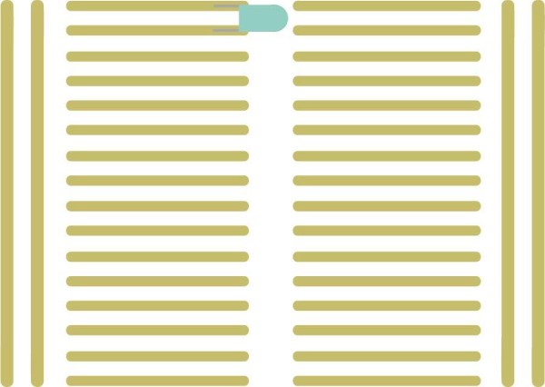
A bread board is excellent for prototyping and requires no soldering.
A bread board has lots of horizontal strips of wire. When components are put in, they act as connecters.
In the image above you can see that the circuit will only continue when a component is between two strips.
Step 8: Tinkercad!

Tinkercad has a circuit designer on board. Just head over to circuits on the left of your projects.
Once you are in, you can build and create prototypes before making them physically.
You can even code your circuits!
Lets create a button and LED
(you can use tinkercad circuits if you don’t have an Arduino)
Step 9: Getting Started
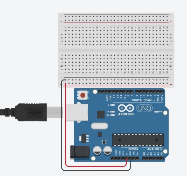
Pull out the Arduino and bread board and lay them out on the work plain.
Next wire 5v to +/positive and then ground to –/negative.
You can colour the wires, but it won’t affect your circuit if you don’t.
Step 10: The Button
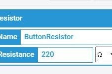
You then need to wire a 220 ohm resistor to the a push button.
Without the resistor the 5v would be too much for the button and the LED.
The resistor must also be wired to positive, as that has the electricity going to it.
You can change the resistance of the resistor in the top right as shown.
Step 11: The LED!
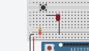
In this step, add an Led to the board rotating it, so that the long leg(anode) is connected to power.
You can rotate the LED at the top left corner.
Put a wire between the push button and the anode leg and then from cathode to negative(ground)
Tinkercad allows you to explore Arduino without the risk of frying your circuit!
Now we are all done.
Click on the run simulation and what your LED illuminate as you press the push button!
Source: Arduino Basics With Night Light