Shadow alarms are usually used for protection against theft. A shadow alarm is a device that sounds an alarm when a shadow falls on it. Described here is a simple circuit of an Arduino-based shadow alarm. This compact shadow alarm unit is capable of sensing a moving shadow in a restricted area, and can be easily installed on a wall, window or door to protect your valuables from theft. Constant lighting is required in the confined area to detect the moving shadow.
Circuit and working
The circuit of Arduino-based shadow alarm is shown in Fig. 1. It consists of an Arduino board, power supply, light-dependent resistor (LDR) sensor, buzzer, relay driver and a few other components. Arduino Uno board is the heart of this circuit.
Arduino. The Arduino is a popular microcontroller platform that has taken the world by storm. It is an Open Source physical computing platform based on a simple yet powerful microcontroller board and development environment to write software for the board.
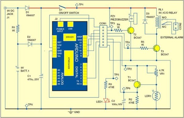
Circuit of Arduino-based shadow alarm
The latest Arduino Uno (refer Fig. 2) is a microcontroller board based on ATmega328. It has 14-digital input/output pins (of which six can be used as PWM outputs), six analogue inputs, a 16MHz crystal oscillator, a USB connection, a power jack, an ICSP header and a reset button. Just connect it to a computer through a standard USB cable or power it from an AC-to-DC adaptor (or battery) to get started.
Note that Arduino Uno board has recently been discontinued and its new version (Arduino Uno R2) is available now. Both can be used for this circuit.
Power supply. The whole circuit can be powered from a universal 9V DC adaptor connected to input jack J1. The 9V PP3 battery (BATT.1) is kept topped up via resistor R1. Capacitor C1 in the power supply section provides clean supply voltage for the microcontroller board and associated circuit. Switch S1 is a power on/off switch. Battery backup is included in the design to ensure that the alarm unit keeps working in case the mains power supply system is tampered with by intruders.
Shadow sensor. Shadow sensor is nothing but a photo resistor, commonly called light-dependent resistor (LDR). The signal from LDR1 is fed to digital input pin 2 of Arduino through transistor T1 (BC547). The input to the Arduino is interpreted with a small delay, introduced by C2. Using variable resistor VR1 you can set the detection sensitivity. Usually, the input level at pin 2 of Arduino is at a logic-low level. Resistor R2 is the pull-down component.
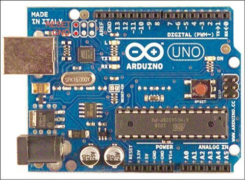
Arduino Uno
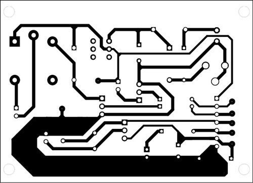
PCB for Arduino-based shadow alarm
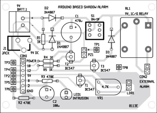
Component layout for the PCB
Download PCB and Component Layout PDFs: Click Here
Download Source Code: click Here
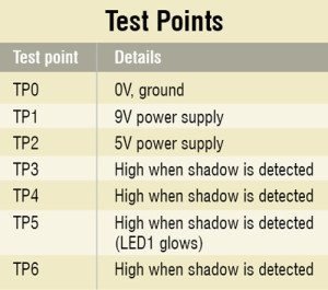
Audio alert and relay switch. When a shadow is detected, logic-high level at the Arduino input terminal (pin 2) enables the alarm unit through the program code. The integrated piezobuzzer PZ1 sounds to indicate that a shadow has been detected by the system.
A more powerful external alarm can be activated through electro-magnetic relay RL1 connected to the digital output terminal (pin 12) of the Arduino board. Transistor T2 drives relay RL1 (9V, 1C/O), which energises for the same duration as the acoustic alarm signal.
The system returns to its normal state (standby mode) when the shadow goes away.
Alert sign. After the alarm stops and the system returns to standby mode, LED1 glows to give a visual indication that the alarm went off at least once. The alert sign activity can be cleared by pressing reset button in the Arduino board.
Software program
The Arduino platform used here underlines the fact that microcontrollers allow lots of functionality to be combined in a single compact case. Because the program (Shadow_Alarm.pde) used here has a relatively simple structure, new features can be easily added to this project with change in the source code file. The control software (Sketch) can be uploaded to the microcontroller through a USB interface to a PC using Arduino IDE. Before uploading the software, remember to remove the external DC power from the microcontroller board and use a standard ‘A to B’ USB cable for connecting to the computer.
Construction and testing
An actual-size, single-side PCB layout for the shadow alarm is shown in Fig. 3 and its component layout in Fig. 4. Enclose the PCB in a tamper-proof cabinet. The shadow sensor should, of course, not be fitted in the same enclosure as the alarm unit. Therefore assemble the shadow sensor on a separate, small PCB and connect it to the alarm unit using a short length of two-core shielded cable. Suggested setup and installation of the shadow alarm is shown in Fig.5.
Read More Detail: Build An Arduino-Based Shadow Alarm