Summary of Arduino Based Egg Plotter
An Egg plotter is a low-cost DIY art robot that draws on spherical objects (eggs, ping pong balls, golf balls). The project uses 3D-printed parts, commonly available mechanical hardware, two stepper motors and a servo, controlled by an Arduino UNO with a CNC shield and A4988 drivers. The guide covers design choices, recommended print settings (PLA, 20% infill, 0.2 mm layers), assembly of the pen-holder hinge and servo, and mounting of stepper motors and egg holders for precise drawing.
Parts used in the Egg Plotter:
- Aluminium profile 20x20 250mm (2x)
- KLF08 Bearing (1x)
- Lead Screw 8mm x 150mm (1x)
- M2 12mm screws (2x)
- M2 nuts (2x)
- M3 30mm screws (2x)
- M3 16mm screw (1x)
- M3 12mm screw (1x)
- M3 8mm screws (13x)
- M3 nuts (7x)
- M4 30mm screws (10x)
- M4 nuts (10x)
- Toilet paper, foam or bubble wrap (cushioning)
- CNC shield (1x)
- Arduino Uno (1x)
- A4988 Stepper Drivers (2x)
- Nema 17 Stepper Motors (2x)
- SG90 Micro Servo (1x)
- Jumpers (6)
- 12V 2A Power Supply (1x)
- Male to Female Jumper Wires (3x)
- Generic 3D printer (for printed parts)
- Drill
- 4.5 mm Drill bit
- Hex Key set
- Wrench set
- Wire Stripper
- Scissor
- 3D printed Pen_Holder_Bottom
- 3D printed Pen_Holder_Top
- 3D printed YZ_Stepper_Holder
- 3D printed X_Stepper_Holder
- 3D printed KLF08_Holder
- 3D printed Egg_Holder_5mm
- 3D printed Egg_Holder_8mm
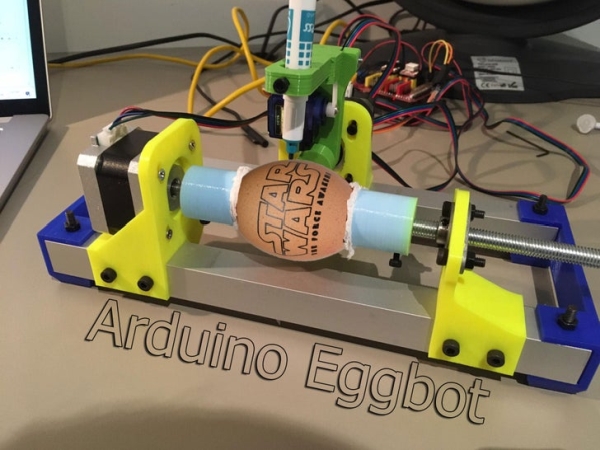
An Egg plotter is an art robot that can draw on spherical shaped objects such as eggs. You could also use this machine to draw on ping pong balls and golf balls.
You can use your imagination with the designs you put on it, you could for example make personalized eggs for Easter.
In this instructable we will not only show you how to make it, but we also created a step by step guide on how to properly use the machine.
I tried to explain this as easy as possible.
This might be the longest instructable you have ever seen/read but I just wanted to make sure that everyone can follow, no matter what their age might be.
Step 1: The Design
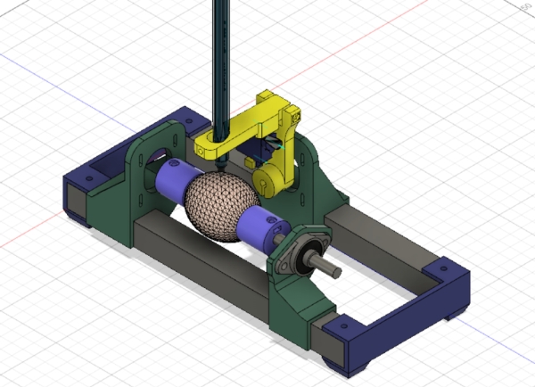
I have spended many hours in fusion 360 designing this thing. I was inspired by the EggBot Pro by EvilMadScientist. Their Eggbot is a well worked out piece of art, but the price is just ridiculous at 325 dollars. So I decided to take on the challenge and I tried to create a sub 100 dollar Eggbot.
I also tried to use as many parts as I had laying around, so if you see a weird choice of hardware, thats why. But if you are bothered by that, feel free to make a remix and share it with us.
What I want to mention is that my Pen Holding mechanism is based on Okmi’s design. I did make some changes, but it looks almost the same.
I think that Autodesk Fusion 360 is the best software for creating these type of projects. It is not only free for students and hobbyists, but it is also well build. Everything just works like it should work. It does take a little bit of time to learn how to work with this software, but once you get the hang of it, it is as easy as it gets. I don’t call myself a pro, but I am very happy with the result I got. When I have to explain this software to someone, I just call it Minecraft for adults.
For the few that are interested in the design, you can find it in the 3D-printing step.
Step 2: Parts
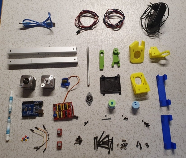
Mechanical components:
- Aluminium profile 20×20*250mm (2x)
- KLF08 Bearing (1x)
- Lead Screw 8mm * 150 (1x)
- M2 12mm (2x)
- M2 Nut (2x)
- M3 30mm (2x)
- M3 16mm (1x)
- M3 12mm (1x)
- M3 8mm (13x)
- M3 Nut (7x)
- M4 30mm (10x)
- M4 Nut (10x)
- Toilet paper, foam or bubble wrap (something that cushions the egg)
Electronics components:
- CNC shield (1x)
- Arduino Uno (1x)
- A4988 Stepper Driver (2x)
- Nema 17 Stepper Motor (2x)
- SG90 Micro Servo (1x)
- Jumpers (6)
- 12V 2A Power Supply (1x)
- Male to Female Jumper Wires (3x)
Tools:
Step 3: 3D Printing
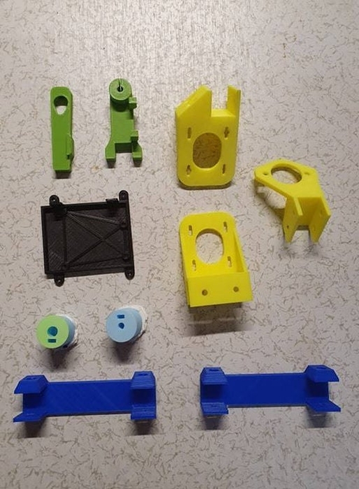
The 3D printed parts are very imported in this project, so make sure you use the right settings. The parts have to be strong enough so nothing bends or brakes and interferes with the quality of the image on our egg.
To start I want to talk about the filament you should use. I would recommend PLA because it is kind of bend resistant. PLA is not heat resistant, but there won’t be much heat dissipated by this machine. You could use PETG that bends more and is harder to break, but I don’t think this advantage is worth the extra money. So if you have some spare PETG, use that. If not, just buy cheap PLA.
The infill I used was 20% for every part. This is not considered super high, but it will get the job done. There won’t be many vibration like in a CNC machine for example so I think 20% is just fine.
As my layer height, I used 0.2 mm. This doesn’t really matter, but the lower you go, the better your print looks and also the longer your print time will take.
As my temperature, I used 200° C on my hot end and my bed was 55° C. This part depends on the type of material that you use.
Supports? For some parts you may need to use some sort of support material, but I think for 70% of the parts, you can just avoid them by orienting them in a proper way.
Also make sure you keep the parts safe and be careful with them. Some of them are very easy to break.
So short summary: use PLA and 20% infill.
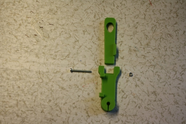
Step 4: Preparing the Pen Holder Part
The first part that we will assemble is the the smallest and trickiest part to build. It is pretty small so if you have big hands, good luck! This part will hold the pen, make the pen go up and down and later on we will attach a second motor that will make the pen rotate. This is actually a crucial part of the machine because this the part that might create a lot of if not attached correctly. But don’t worry it is actually pretty easy and I have token a lot of pictures. I also added a parts list for this specific part and split it up into multiple steps:
- SG90 Micro servo with accessories
- 1* M3 30mm
- 1* M3 12mm
- 2* M3 nut
- 2* M2 12mm
- 2* M2 nut
- Pen_Holder_Bottom (3D printed)
- Pen_Holder_Top (3D printed)
Step 1: Create the hinge
The hinge that will lift up the pen is created by the M3 30mm screw. Just line the parts up so you can see trough the hole and push the screw in and attach it on the other side with the M3 nut.
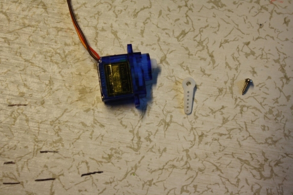
Step 2: Preparing the Servo
We will need to attach a servo horn to the servo. This is the small white plastic part. Make sure you use the right one like in the images. The horn should come with your servo as well as the screw that attaches the horn to the servo.
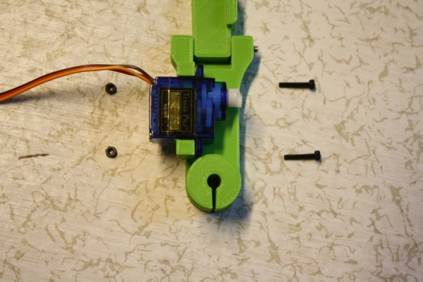
Step 3: Attach the servo to the Scissor parts
Now that our servo is ready, we can attach it to the Pen Holder. Just line up the servo like in the images and use the M2 12mm screws and nuts to keep it in place.
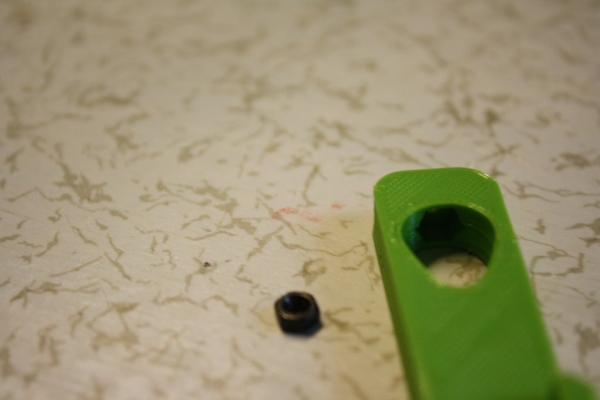
Step 4: Add the pen holding screw
On the top of the part, there is a hole specially made for a nut. Place the nut in there and screw in the last M3 12mm screw from the back. This is a mechanism that will clamp our pen so it doesn’t move when we are printing something onto our egg.
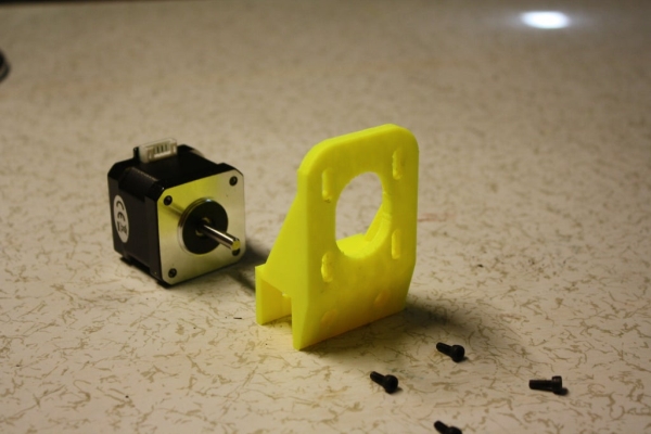
Step 5: Attaching Stepper Motors
In this step, we are going to attach the stepper motors to their correct holders. The stepper motors will make the egg rotate and make the pen move to the right and left. We will also add the part that holds the bearing which will make the egg move even smoother.
For this step you will need:
- 10* M3 8mm
- 3* M3 16mm
- 5* M3 nut
- 2* Nema 17 Stepper Motor
- 8mm Lead Screw
- YZ_Stepper_Holder (3D Printed)
- X_Stepper_Holder (3D Printed)
- KLF08_Holder (3D Printed)
- Egg_Holder_5mm (3D Printed)
- Egg_Holder_8mm (3D Printed)
Step 1: Attach XY-Stepper Motor
The Stepper motor that will control the YZ planes has to attached to the 3D Printed YZ_Stepper_Holder. I designed the part so the height of the stepper motor can be adjusted. I recommend to put them in the middle and adjust it later on if neccesary. You have to use 4* M3 8mm screws to attach the stepper motor and make sure that the connector (white piece of stepper motor) is facing upwards.
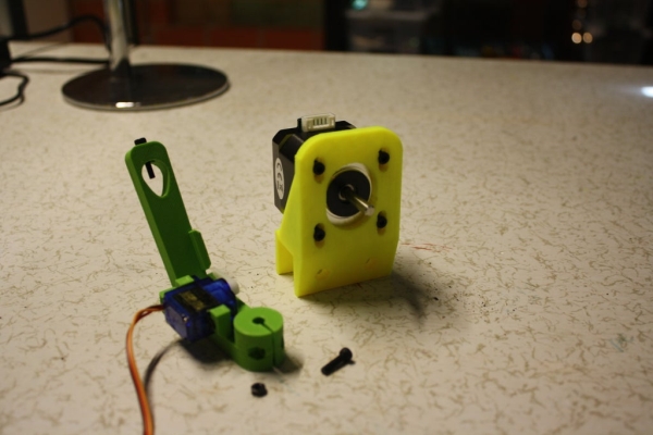
Step 2: Attach Y-Axis
The hinge part, pen holder or Z-axis can now be attached to this Stepper Motor by using a M3 Xmm screw and an M3 nut. The screw and nut will act like a little clamp and hold the pen holder in place. Make sure there is a little gap between in my case the yellow and green part. The pen holder needs to move smoothly withouth touching anything.
Step 3: Attach X-Stepper Motor
The Stepper motor that will control the X plane has to attached to the 3D Printed X_Stepper_Holder. I designed the part so the height of the stepper motor can be adjusted. I recommend to put them in the middle and adjust it later on if neccesary. You have to use 4* M3 8mm screws to attach the stepper motor and make sure that the connector (white piece of stepper motor) is facing upwards.
Source: Arduino Based Egg Plotter
- What objects can the Egg Plotter draw on?
It can draw on eggs, ping pong balls, and golf balls according to the article. - What controller and drivers are used for the electronics?
The project uses an Arduino Uno, a CNC shield, and A4988 stepper drivers. - Which motors are required for the Egg Plotter?
The build uses two Nema 17 stepper motors and one SG90 micro servo. - What filament and print settings are recommended for 3D parts?
PLA is recommended with 20% infill, 0.2 mm layer height, 200°C hot end and 55°C bed as used by the author. - How is the pen lifted and clamped in the pen holder?
The pen holder uses an M3 30mm hinge screw and a servo horn; a nut and M3 12mm screw clamp the pen in place. - Are supports required for 3D printed parts?
Some parts may need supports but about 70% can be printed without supports by proper orientation. - What mechanical parts are used to support the egg rotation?
An 8mm lead screw, KLF08 bearing, and printed egg holders (5mm and 8mm) are used to support and rotate the egg. - What power supply does the project use?
The project uses a 12V 2A power supply as listed in the electronics components.