
Monitoring the temperature of a transformer or electric motor winding involves data acquisition. This project is developed to monitor the temperature of an electric motor and a transformer with high accuracy, incorporating display and alarm facility. This circuit can be installed near a transformer winding or a motor’s location, or it can be attached to either of these using suitable support. It can track the temperature of the device or equipment and its surroundings. It also generates an alert at the time of rise in temperature with the help of Alarm Generator.
The project includes LM35 temperature sensor to detect the temperature in the device (transformer/motor), buzzer to alert abnormal condition in the device and LCD (LCD1) to display the current status of the device. The author’s prototype is shown in Fig. 1.
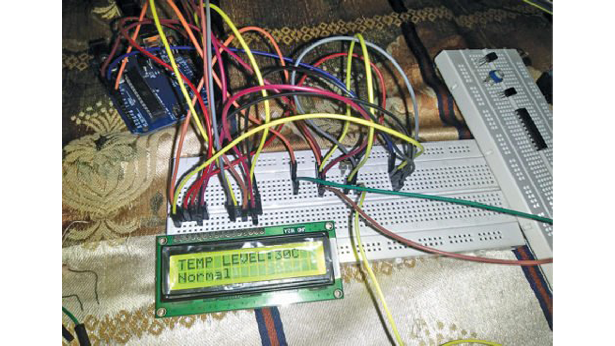
Author’s prototype
Transformers and electric motors are the most significant sources of electrical power and industrial systems. Failure of these devices could cause electrical power outages, environmental health hazards and more. Failure can happen due to various reasons, including dielectric failure, winding deformation, short-circuit, magnetic circuit, electrical disturbance, distortion of insulation, lightning, insufficient maintenance, slack connection and overloading.
Functional life of these devices is evaluated by their capability to dissipate the generated heat to the surrounding environment. Evaluation of temperatures can provide an insightful diagnosis of the devices.
The penalty for temperature rise may not be sudden, but gradual, as long as it is within break-down limit. Among these consequences, insulation degradation is important. Since insulation is costly, its deterioration is unwanted. Determination of oil temperature and winding insulation system temperature is critical.
Circuit and working for coil winding temperature recorder and alarm generator
The circuit diagram of the coil winding temperature recorder and alarm generator is shown in Fig. 2. It comprises LCD1 (16×2), Arduino Uno, piezo buzzer (PZ1), resistor (220-ohm), preset (10-kilo-ohm) and 9V battery.
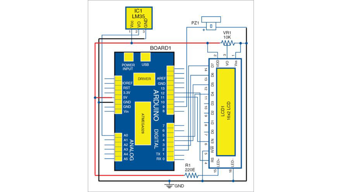
Circuit diagram of coil winding temperature recorder and alarm generator
LM35
It provides linear output proportional to temperature, with 0V corresponding to 0°C and output voltage change of 10mV for each °C change. It is easier to use than a thermistor and a thermocouple.
Output of LM35 can be connected directly to Arduino analogue input. Since Arduino analogue-to-digital converter (ADC) has a resolution of 1024 bits, and reference voltage is 5V, the equation used to calculate the temperature from ADC value is:
temp = [{5.0×analogRead (TemperaturePin)}/1024]×100.0
LCD
A 16×2 liquid crystal display (LCD1) is used to display the temperature. Various messages displayed on LCD1 are given in the testing section.
Buzzer
The piezoelectric buzzer produces sound based on reverse piezoelectric effect. Generation of pressure variation or strain by the application of electric potential across a piezoelectric material is the underlying principle.
The buzzer can be used to alert a user of an event corresponding to a switching action, counter signal or sensor input. It consists of piezo crystals between two conductors. When a potential is applied across these crystals, these push on one conductor and pull on the other. This push-and-pull action results in a sound wave.
Arduino Uno
Arduino Uno is a microcontroller (MCU) technology based on ATmega328 series. It contains 14 digital input/output pins (of which six can be used as PWM outputs), six analogue inputs, one 16MHz crystal oscillator, USB connection, power jack, ICSP header and reset button. (Arduino Uno R3 was used during testing.)
Preset
A preset is a three-terminal variable resistor with a rotating contact that makes an adjustable voltage divider. If only two terminals are utilised, one end and the wiper, it behaves like a variable resistor or rheostat. Here, it is used to control the contrast of LCD1.
Software
Programming is done on Arduino version 1.8.6 integrated development environment (IDE). Analogue pins A0 to A5 on Arduino Uno are analogue input pins. After running the code, you will see voltage values on the serial monitor of the PC.
LM35 sensor is connected to pin A0, and the buzzer is connected to pin 9 of Arduino Uno, respectively.
Download Source Code
Construction and testing
Make connections as per the given circuit diagram. Place the sensor near the device to be monitored. Connect 5V USB power supply to Arduino board. Alternatively, you can use a 9V battery at Vin pin of Arduino Uno. Recorded temperature level will be displayed on LCD1.
Whenever there is a low temperature, below 10°C, ‘Low’ will be displayed on LCD1 along with a buzzer sound. If temperature is between 10°C and 40°C, ‘Normal’ will be displayed. If temperature is between 40°C and 100°C or above, ‘High’ or ‘Very high’ will be displayed on LCD1.
Read More Detail:Arduino-Based Coil Winding Temperature Recorder and Alarm Generator