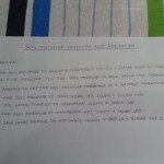
INTRODUCTION & OBJECTIVES:
I am a basic system that utilizes Arduino for automating the watering of small potted plants or crops.
This system monitors soil moisture levels by using LEDs for indications and emitting an alarm beep if the soil is dry. If the soil is dry, the irrigation system will be triggered to pump water for watering plants.
The system utilizes an LCD screen to update on ongoing actions and a real-time clock.
The Theory (as per Wikipedia):
The amount of water within a substance, like soil, rocks, ceramics, fruit, or wood, is known as water content or moisture content. Water content is utilized across various scientific and technical fields, and is represented as a ratio that can vary from 0 (completely dry) to the porosity value of the materials when saturated. It can be provided based on volume or mass (gravimetric).
The mathematical definition of volumetric water content is given by the symbol θ.
where is the volume of water and is the total volume (that is soil volume + water volume + air space).
Gravimetric water content[1] is expressed by mass (weight) as follows:
where is the mass of water and is the bulk mass. The bulk mass is taken as the total mass, except for geotechnical and soil science applications where oven-dried soil (, see the diagram) is conventionally used as .
To convert gravimetric water content to volumetric water, multiply the gravimetric water content by the bulk specific gravity of the material.
In soil mechanics and petroleum engineering, the term water saturation or degree of saturation, is used, defined as
where is the porosity and is the volume of void or pore space. Values of Sw can range from 0 (dry) to 1 (saturated). In reality, Sw never reaches 0 or 1 – these are idealizations for engineering use.
The normalized water content, , (also called effective saturation or ) is a dimensionless value defined by van Genuchten[2] as:
where is the volumetric water content; is the residual water content, defined as the water content for which the gradient becomes zero; and, is the saturated water content, which is equivalent to porosity, .
Step 1: Arduino Automatic Watering System HARDWARE & MATERIALS
To accomplish this Arduino Automatic Watering System project, you will need:
1 x Arduino UNO MEGA Duemilanove or Teensy 2.0 +
1 x LCD display with I2C communication
1 x RTC module with I2C communication
1 x Relay Module opto-coupled to 250V/10A
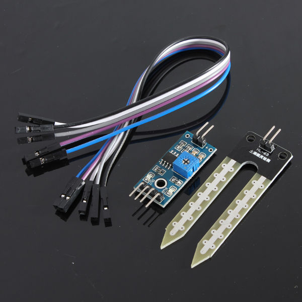
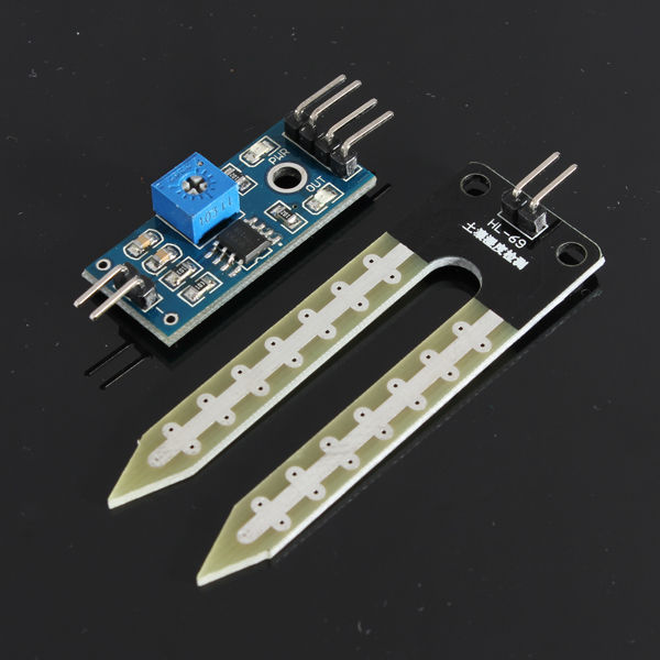
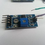
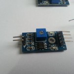
2 x Modules “Driver” LM-393 general purpose
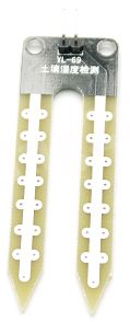
1 x Soil Moisture Sensor (Hygrometer) KDQ11
1 x Water Level Sensor (Homemade)
1 x Buzzer piezoelectric
2 x LEDs – 10mm, Green
1 x LED – 10mm, Red
1 x LED – 10mm, Yellow
4 x Resistors 150 Ohm 1/4 W
1 x Water pump for aquarium, with filter system (127 or 220V)
1 x Electric Power Cable, 127/220VAC – 10Amps
1 x Socket 127/220VAC – 10 Amps
Wires and cables for connections and communication
You can purchase the soil moisture sensor and “Driver” on ebay.
http://www.ebay.com/itm/KDQ11-MOISTURE-SENSOR-KIT-URBAN-GARDEN-TOOL-SOIL-MOISTURE-SENSOR-SCA-1703-/221227848188?pt=LH_DefaultDomain_0&hash=item33823511fc
You can purchase the soil moisture sensor and “Driver” on ebay.
http://www.ebay.com/itm/1-Channel-5V-Relay-Module-Shield-for-Arduino-uno-1280-2560-ARM-PIC-AVR-DSP-/271117672120?pt=LH_DefaultDomain_0&hash=item3f1fdf5eb8
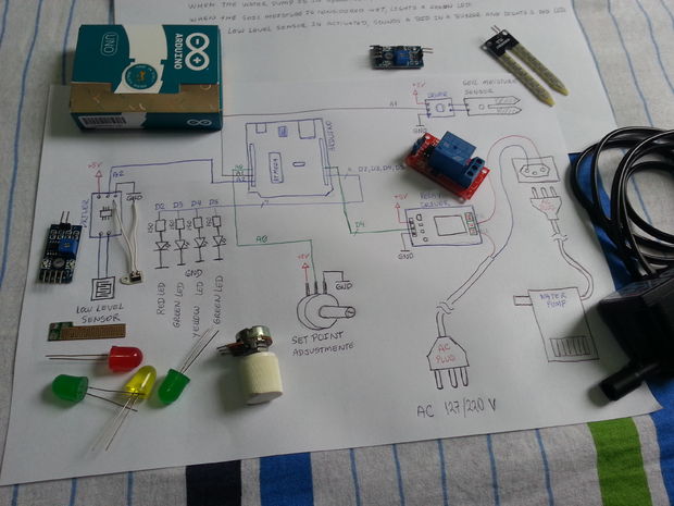
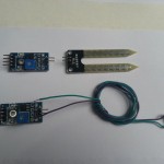
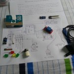
Step 2: Arduino Automatic Watering System COMPONENTS


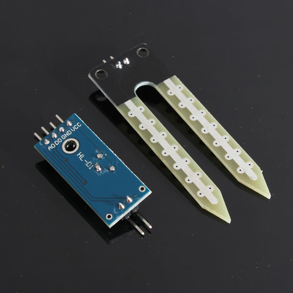
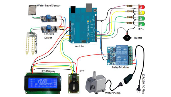
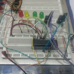
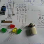
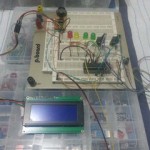
In the Pictures you have an overview of the components used.
Data from the soil moisture sensor set:
When the soil is dry, the impedance will be high and the LM-393 will show a high value on the output.
When the soil is wet, it will show a low value in the output.
The 3 LEDs range can be defined as:
– Soggy soil – moisture between 0 and 500;
– Wet soil – moisture between 500 and 800;
– Dry soil – moisture between 800-1023;
The module has one digital output and an analog output. (in the project, should be used to analog output)
The water level sensor:
This sensor must be made (homemade) on phenolite board, with spacings of 1 mm between trails and trails with 1 mm of thickness.
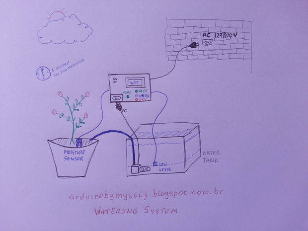
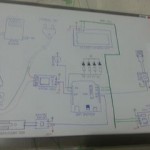
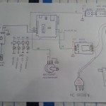
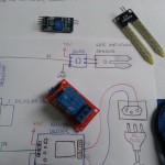
Step 3: Arduino Automatic Watering System INTERCONNECTION & DIAGRAM:


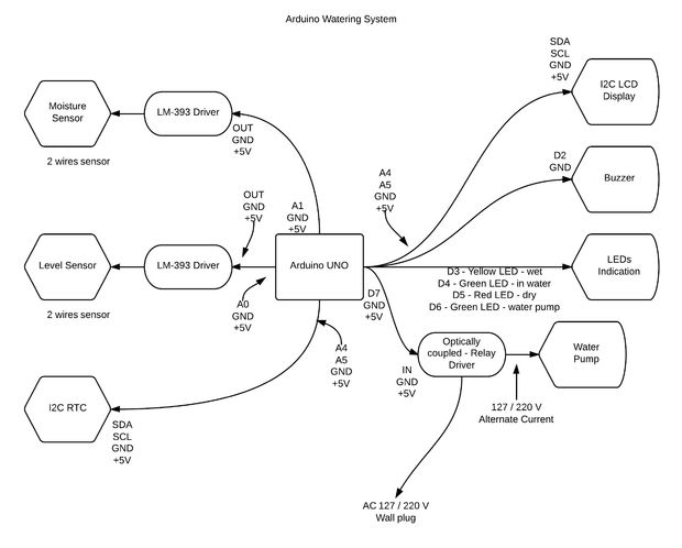
1 – a block diagram;
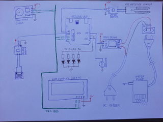
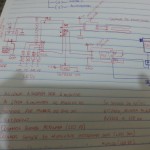
2 – an interconnection diagram (in manuscript);
3 – a wiring diagram;
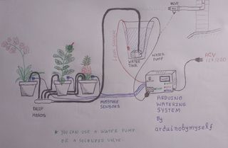
4 – usability principlesThese diagrams are describing the main system interconnections.You can get the original of this file by accessing the “GOOGLE driver” below:https://docs.google.com/file/d/0B_YlEklLDDS7SllRMzUyQlhHVDg/edit?usp=sharinghttps://docs.google.com/file/d/0B_YlEklLDDS7RkNMZko2ckhLcUU/edit?usp=sharinghttps://docs.google.com/file/d/0B_YlEklLDDS7Ym52UE1qcGlqQVE/edit?usp=sharinghttps://docs.google.com/file/d/0B_YlEklLDDS7Z3hZY3pNZ0NWZG8/edit?usp=sharing*********************************************************************************************************************************************
*********************************************************************************************************************************************
Please, fix an error in your “interconnection diagram (in manuscript)” diagram:
The level sensor must be connected to pin A0 of Arduino and the soil moisture sensor must be connected to pin A1 of arduino.
*********************************************************************************************************************************************
*********************************************************************************************************************************************Description of the main connections:
RTC <-> Arduino:
GND <-> GND
+5 V <-> +5 V
SDA <-> A4
SCL <-> A5Relay <-> Arduino:
GND <-> GND
+5 V <-> +5 V
IN <-> D7LCD <-> Arduino:
GND <-> GND
+5 V <-> +5 V
SDA <-> A4
SCL <-> A5BUZZER <-> Arduino:
+ <-> D2
– <-> GNDLM-393 DRIVER (moisture sensor) <-> Arduino
GND <-> GND
+5 V <-> +5 V
OUT <-> A1LM-393 DRIVER (water sensor level) <-> Arduino
GND <-> GND
+5 V <-> +5 V
OUT <-> A0Other Components <-> Function <-> Arduino
Red LED <-> Dry soil <-> D5
Yellow LED <-> Soggy soil <-> D3
Green LED <-> Moist soil <-> D4
Green LED <-> Water Pump <-> D6
Step 4: Arduino Automatic Watering System SOFTWARE & PROGRAMMING

You can download freely the code for this project in the “GOOGLE driver”:
https://docs.google.com/file/d/0B_YlEklLDDS7T3JFX…
Or on the GitHub:
Arduino Watering System Files
Any problems, questions and suggestions, please send an email to:
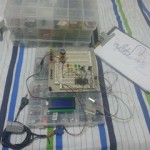
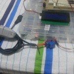
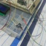
Step 5:Arduino Automatic Watering System TESTS & ADJUSTMENTS
In the image, there is a demonstration of how the system operates and the proper way to conduct tests.
It makes sense that since the system has a preset hour for operation, you can modify the time using software for when the tests will be conducted, and later you can fine-tune the operational “time”.
Step 6:Arduino Automatic Watering System VIDEOS & PHOTOS:
Questions and suggestions send to: [email protected]
Part 1:
Part 2:
Part 3: