
Summary of Arduino 2.4 GHz Spectrum Analyser
This article details a portable 2.4–2.5 GHz Wi-Fi spectrum analyzer using the Cypress CYWM6935 module and an Arduino ATmega328. Designed as a diagnostic tool, it plots signal strength across 84 MHz-wide steps on a Nokia 5110 LCD. The device features a MODE button to switch between frequency and channel views, powered by a 3.7V Li-ion battery regulated to 3.3V.
Parts used in the 2.4 GHz Spectrum Analyser:
- Cypress CYWM6935 Wireless Radio Module
- Arduino ATmega328 microcontroller
- Nokia 5110 LCD display (84x48 pixels)
- MCP1702-330E 3.3V LDO regulator
- AA-sized 3.7V rechargeable lithium battery
- MODE push button
- Slide switch for power control
- 10K resistor
- 270R series resistor
- Breadboard adapter (2mm to 0.1 inch)
This article describes a simple spectrum analyser for the 2.4 to 2.5 GHz Wi-Fi band. It’s based on the Cypress CYWM6935 Wireless Radio Module. Although the manufacturer doesn’t recommend it for new commercial projects, it is still widely available from eBay suppliers and Farnell here in the UK. The module has 1 MHz channel spacing which is a bit ‘coarse’ for a full-blown spectrum analyser but it’s good enough for this project’s intended purpose, namely as a quick diagnostic tool to check for interference causing problems to a router’s Wi-Fi signal. A spectrum analyser differs from the Wi-Fi “sniffer” type Apps available for Android devices because, unlike those Apps, a spectrum analyser will plot everything it receives – not just Wi-Fi signals – without attempting to read or “decode” them. A spectrum analyser is only interested in the relative strength of the received signal, not in any data the signal may be carrying.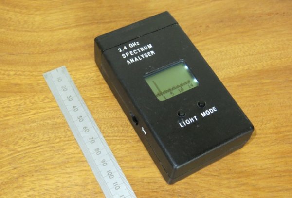 Although there are other radio modules for the Wi-Fi band, I chose the Cypress CYWM6935 because I wanted a small, portable stand-alone device using its own LCD display. The CYWM6935 module is easily availalable and its 1 MHz-wide steps means there are exactly 84 steps in the Wi-Fi band: 2400 MHz to 2483 MHz. The Nokia 5110 LCD display is 84 pixels wide so it’s a perfect match with a horizontal scale of 1 pixel per MHz.
Breadboarding the CYWM6935 Module
One slight difficulty with the CYWM6935 Module is that it’s fitted with a 6 way x 2 row 2mm header which makes it difficult to breadboard. The following photos may be useful for anyone who wants to make their own 2mm to 0.1″ adapter. I pushed the header pins through their plastic carrier until they were almost flush on the top side. The 2mm socket fits comfortably between the header pin’s standard 0.3″ DIL spacing.
Circuit Diagram of the CYWM6935-based Spectrum Analyser
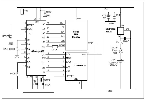
The radio module uses an SPI interface to access its registers so Arduino pins D13, D12 and D11 have to be used for the hardware SPI interface – SCK, MISO and MOSI respectively. It’s convenient for the PCB layout to use adjacent Arduino pins (D10, D9 and D8) for the radio’s active low inputs: Power Down (nPD), Select Signal (nSS) and nRESET.
In practice, the radio module’s nPD pin could just be tied to Vcc though a 10K resistor but I chose to connect it to an Arduino output in case I wanted to experiment further with the module’s POWER_DOWN mode.
I had intended to power down the Arduino by putting it in POWER_DOWN sleep mode which would also power down the display and the radio. Unfortunately, I couldn’t get the radio module’s power-down current less 0.45mA (despite the datasheet claiming <1µA), so I settled for a conventional power on/off slide switch instead.
The function of each of the radio’s pins is shown in Table 1 in the Radio Module’s documentation. A full list of all the CYWM6935 chip’s registers is shown in the CYWUSB6935 Chip’s Datasheet.
I connected the Nokia 5110 84×48 LCD display to the ATmega328’s analogue pins, configured as digital outputs, purely for convenience in laying out the printed circuit board as the project doesn’t need any analogue inputs.
The MODE push button, connected to Arduino input D7, simply changes the displayed scale from 2.4 ~ 2.483 GHz to Wi-Fi channel numbers 1 ~ 14. It also switches on or off the option to display the peak signal strength of each 1 MHz RF channel in addition to the instantaneous values. It’s purely ‘cosmetic’ in the current design and doesn’t change the receiver’s measurement parameters at all. There’s not a lot more you can display in the limited space on the Nokia 5110’s 84×48 screen.
I powered the circuit with an AA-sized 3.7v rechargeable lithium battery nominally rated at 1000 mAh. As a fully-charged lithium battery is 4.2v and the CYWM6935 radio module is, reputedly, not very tolerant of excessive voltage, I included a 3.3v LDO regulator to power the entire circuit. The MCP1702-330E regulator has a very low quiescent current (typically 1.6 µA) with a dropout voltage around 25mV at the sort of current our circuit takes (about 50mA including the LCD backlight), so very little of the battery’s charge is wasted by using the regulator.
The Printed Circuit Board
The Nokia 5110 Display
Note that the pinout of the Nokia 5110 displays varies depending on the supplier so the PCB may need some modification. Most of the pins are connected to ATmega328 outputs so some manoeuvring is possible by re-defining the pins in the Arduino sketch. Vcc, GND and LIGHT's 270R series resistor are the only ‘hard-wired’ connections for which the PCB would need modifying.
The type of display can be distinguished by looking at the tracks on the back of the board. I designed the PCB for the type of display shown on the left, below. I’d suggest getting the display before designing the PCB.
I designed the PCB layout using Circuit Wizard. You can download the layout here. (The breadboard adapter layout can be downloaded here.)
For more detail; Arduino 2.4 GHz Spectrum Analyser
- What is the primary purpose of this spectrum analyser?
It serves as a quick diagnostic tool to check for interference causing problems to a router's Wi-Fi signal. - How does this device differ from Wi-Fi sniffer apps?
Unlike sniffer apps that decode data, this analyser plots everything received based only on relative signal strength without attempting to read or decode signals. - Why was the Cypress CYWM6935 module chosen?
The author chose it for its small size, portability, standalone capability with an LCD display, and its 1 MHz channel spacing which matches the 84-pixel width of the Nokia 5110 screen. - How many steps are available in the Wi-Fi band for this project?
There are exactly 84 steps covering the range from 2400 MHz to 2483 MHz due to the 1 MHz channel spacing. - Which Arduino pins are used for the hardware SPI interface?
Pins D13, D12, and D11 are used for SCK, MISO, and MOSI respectively. - What type of power source is used and how is it regulated?
A 3.7V AA-sized rechargeable lithium battery powers the circuit, regulated down to 3.3V using an MCP1702-330E LDO regulator. - Can the radio module be put into sleep mode?
The author intended to use POWER_DOWN sleep mode but settled for a slide switch because the current could not be reduced below 0.45mA despite datasheet claims. - What function does the MODE push button serve?
It changes the displayed scale between 2.4 to 2.483 GHz and Wi-Fi channel numbers 1 to 14, and toggles the display of peak signal strength.
