Overview
In this lab, you’ll learn how to connect a variable resistor to a microcontroller and read it as an analog input. You’ll be able to read changing conditions from the physical world and convert them to changing variables in a program.
(:toc Table of Contents:)
Parts
For this lab you will need to have the following parts:
Prepare the breadboard
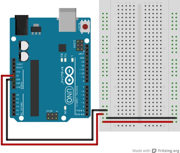
Conect power and ground on the breadboard to power and ground from the microcontroller. On the Arduino module, use the 5V and any of the ground connections:
Add a potentiometer and LED
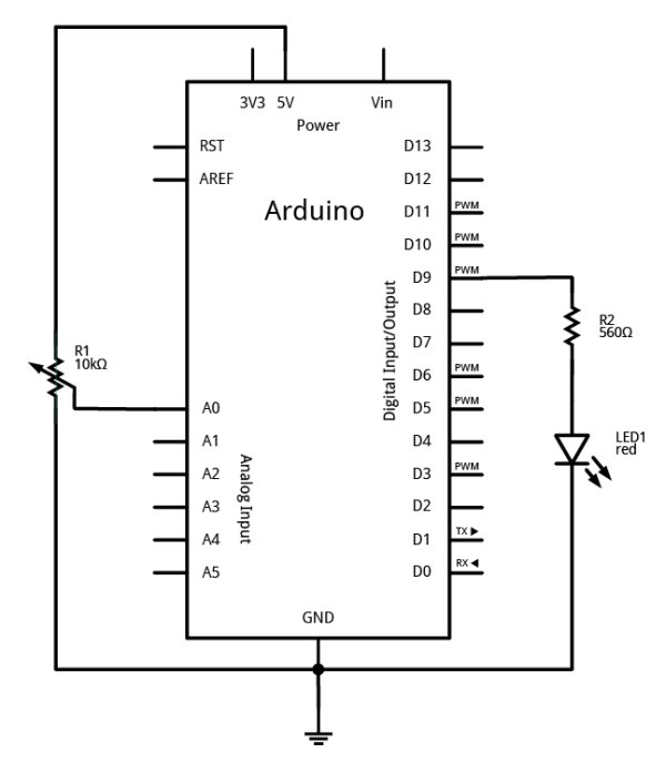
Connect a potentiometer to analog in pin 0 of the module, and an LED to digital pin 9:
Program the Module
Program your Arduino as follows:
First, establish some global variables: One to hold the value returned by the potentiometer, and another to hold the brightness value. Make a global constant to give the LED’s pin number a name.
In the setup() method, initialize serial communications at 9600 bits per second, and set the LED’s pin to be an output.
In the main loop, read the analog value using analogRead() and put the result into the variable that holds the analog value. Then divide the analog value by 4 to get it into a range from 0 to 255. Then use the analogWrite() command to face the LED. Then print out the brightness value.
When you run this code, the LED should dim up and down as you turn the pot, and the brightness value should show up in the serial monitor.
For more detail: Analog In with an Arduino


