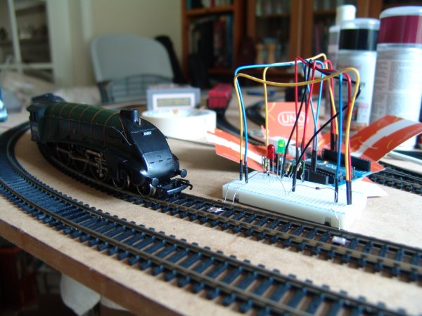
Summary of An Arduino Powered (Scale) Speed Trap
The article describes a project to measure the speed of model trains accurately using an Arduino-based speed trap. The creator used two light-dependent resistors (LDRs) as sensors placed a known distance apart on the track. When a train passes, the system records the time between the LDRs being triggered, calculates speed, and signals via LEDs if the train is over or under the speed limit. Data is also sent to a PC for display. The project combines simple hardware with Arduino programming to provide realistic speed monitoring for model railways.
Parts used in the Arduino Powered Speed Trap:
- Arduino microcontroller
- Two light dependent resistors (LDRs, 1.8k-4.5k Ohm)
- Two LEDs (green and red)
- Various resistors (for LED circuits and voltage dividers)
- Connecting wires
- Breadboard or prototyping board (implied)
After a break of around two decades I’ve recently started building a model railway. One of the issues I’ve faced is trying to work out how fast I should be running the trains so that their speed reflects reality given the scale at which they are modelled. I’m guessing the details won’t interest everyone reading this post but if you are interested then I’ve blogged about this from the model railway side on one of my other blogs. Suffice it to say that what I needed was to be able to measure the time it took for a model locomotive to travel a certain distance.
Now I could have used a ruler and a stop watch but this would never be very accurate. So being me I turned to a more computer oriented solution: an Arduino powered speed trap!
The brief I set myself was simple:
- two switches to measure the time taken to travel a given distance
- a green LED to signify the train was travelling below a given speed limit
- a red LED to signify the speed limit was being broken
- full speed details passed back to the PC for display
The main question was what form of switches should I use. Physical switches were out as I would never be able to accurately place them on the track in a way that any locomotive would be able to trigger them without incident. A reed switch would be easy to use and to hide on the layout, but would mean adding a magnet to each locomotive which seemed a bit daft. An infrared beam across the track would also work, but hiding it on the layout would be difficult. In the end the only sensible idea I could come up with was using a light dependent resistor (LDR) and watching for a sudden change in resistance as the light was blocked by the moving locomotive.
So on my way home on Thursday I called in at my local Maplin store and bought two of the smallest and flattest LDRs they had (specifically the 1.8k-4.5k version).
Now while I knew that the more light you shine on an LDR the less resistance it has I wasn’t sure of the best way of making use of this information in conjunction with the Arduino. Fortunately the web is awash with information and tutorials and I quickly came across the solution.
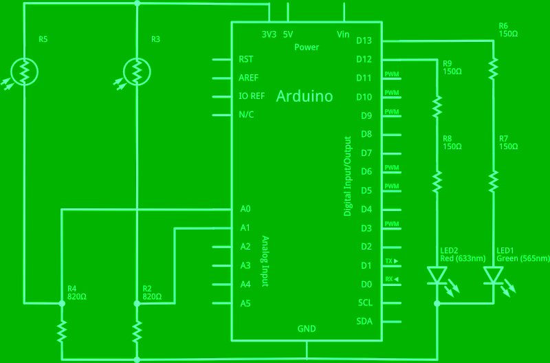
So with my two LDRs, two LEDs and a bunch of resistors I knocked together the following (note that both views were generated at the same time using Fritzing, I really am impressed by this application).
As you can probably see this is a little more complicated than it needs to be as it uses two resistors for each LED, but this was the best I could manage with the resistors I had.
Of course the hardware is only half of the solution. Without appropriate microcode the Arduino isn’t going to do anything useful. Fortunately I’m better at writing software than I am at designing circuits so this half was easier.
The code is (fairly) straightforward. Essentially it’s a state machine that (ignoring invalid inputs) follows the following steps:
- wait until sensor 1 is triggered
- when sensor 1 is triggered record the time
- wait until sensor 2 is triggered
- determine the time difference between the two sensors being triggered and use this to calculate the speed of the locomotive
- wait until both sensors have returned to normal then return to step
For more detail: An Arduino Powered (Scale) Speed Trap


