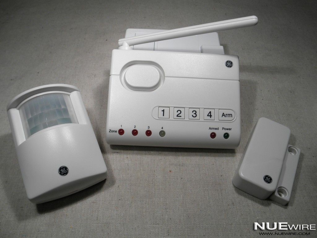
This project will add tweeting capabilities to the GE 45142 Choice-Alert Wireless Control Center Alarm system. The alarm system allows you to connect up to 16 different sensors across 4 zones and with the addition of the Arduino powered Alarming Tweet you can enable it to keep you informed of it’s status anytime anywhere.
Originally I was thinking about building a motion detecting sensor system from scratch for the Adafruit Make it Tweet contest, but after thinking about what I would need to assemble to build it I figured there must be an easier solution. I started looking around for pre-built home security sensors etc… when I stumbled upon the GE Choice-Alert Wireless alarm system. I figured why not let it do all the heavy lifting of monitoring the sensors then I only need to figure out a way to make it tweet. Since the LEDs indicate the status of the sensors and alerts all I really needed was a way to monitor them and then send the results to Twitter.
If this sounds interesting keep reading to find out how to build one yourself. Before we get started lets go over the material we will need:
1 x GE 45142 Choice-Alert Wireless Control Center with Door or Window Sensor Kit from Amazon, Lowes or Home Depot ($30 -$40) – Comes with a single magnetic sensor for doors/windows many other sensors can be added ($15-$25 each)
1 x Arduino UNO from Adafruit ($30)
1 x Arduino Ethernet Shield from Adafruit ($45)
1 x 9V regulated DC wall-power adapter from Adafruit ($7)
1 x Arduino Project Enclosure from Sparkfun ($12)
1 x Right Angle Male Header strip from Sparkfun ($2)
Length of Cat 5 cable
Heat shrink tubing
Happy building,
willnue
Step 1: Open the Control Center case
Remove the 4 screws holding the Control Center case together then remove the 2 screws holding the circuit board onto the case. Be careful not to pull of the antenna or speaker wires.
We are interested in the LED leads protruding from the bottom of the circuit board.
Step 2: Prepare the Control Center
From my testing it appears the Control Center sends roughly 3.3 volts to each LED continuously on the anode and then sinks the current on the cathode when it wants to light up the LED. To read the state of the LED we will connect a wire to the anode and monitor it using an Analog pin on the Arduino. When the LED is not lit we will read about 3.3v and when it is lit we will read little < 0.5v or no voltage as the current sinks through the LED.
Once the case is opened we need to solder 7 wires onto the Control Center circuit board. 1 wire for each of the 6 LEDS and 1 for ground. For the LEDs we are going to solder the wires onto the pin of each LED that is farthest away from the edge of the circuit board. Be careful not to bridge the connection between the two pins when soldering. For the ground we will need to flip the board over and solder it to the outer pin of the barrel jack.
Try to keep the wires as short as possible and route them along the edge of the board to the side with the antenna. After soldering, drill a hole through the back of the case and feed the cable through as shown.
It’s helpful to write down which wire is connected to which LED.
Note: The white residue on the board was present from the factory.
Step 3: Connect the Arduino
Slide some heat shrink tubing over the cable then break off a row of 6 right angle headers and solder the 6 LED wires to them. Once soldered cover the wires with hot glue for insulation then add and shrink some additional tubing to cover. This will provide a good solid connecter for plugging into the Arduino. Be careful when shrinking over the hot glue as it will remelt if it gets too hot. Repeat the same process for the ground wire with a single header then slide the heat shrink tubing up the cable shrink everything together.
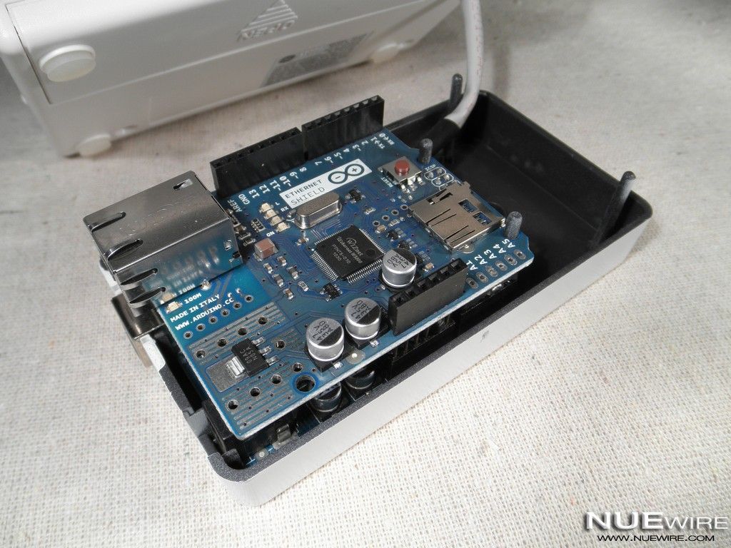
Since the Arduino project enclosure doesn’t really allow for much to be added above and beyond the Ethernet shield we need to make a few modifications to it. We need to remove the 6 female header block from the analog pins and also clip off one of the GND pins. Once completed plug in the Control Center cable and stack the Ethernet shield on top.
Step 4: Close up the cases
Step 5: Configure ThingTweet
Unfortunately since Twitter has switched to OAuth authentication getting an Arduino to send tweets directly to Twitter from an Ethernet shield has become much more difficult than in the past. For the time being it seems the easiest way to circumvent the issue is to use a proxy between the Arduino and Twitter. The good news is using a proxy allows for better control on the Twitter side and simplifies the code required on the Arduino quite a bit.
For my project I chose to use ThingTweet from ThingSpeak as the proxy between my Arduino and Twitter, mostly because I already had a ThingSpeak account and enjoy the service. Getting the Arduino to send it’s first tweet took me only a few minutes to implement with ThingTweet. To get set up yourself check out the great Update Twitter with ThingTweet and Arduino + Ethernet Shield tutorial the ThingSpeak team created, which also includes a sample Arduino sketch.
Note: The code in the next step is based on ThingTweet, but it should be easily updated for any Twitter proxy.
For more detail: AlarmingTweet Using Arduino