Step 1: Prepare Your Materials
For this project, you will need the following materials:
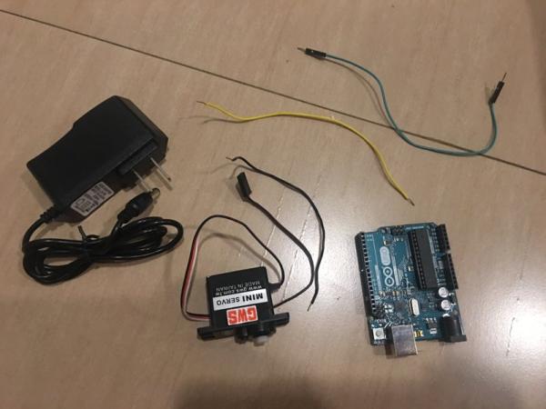
- For the circuit:
- 3 pieces of Insulated copper wire (22AWG wire) around 4-6 inches long, stripped on both ends
- AC/DC Adaptor
- GWS Mini Servo
- Double Side Servo arm
- Servo screw (1.7 x 3mm)
- Arduino
- USB Cable A to B
- For building the encasing:
- 2mm clear acrylic sheets (or any colored sheets of your choice)
- Tamiya cement glue
- OR Glue gun
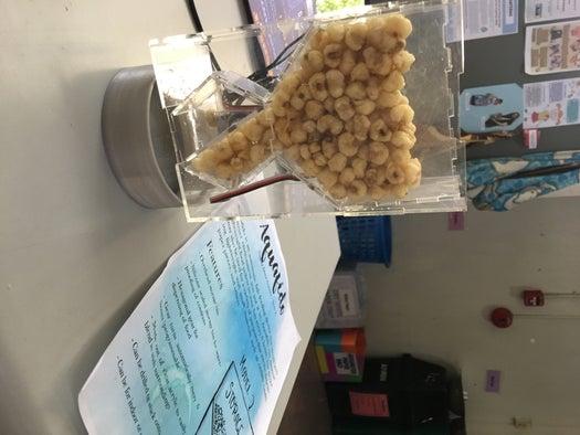
Step 2: Laser Cut the Food Storage
First, you will want to laser cut the fish food storage bin or the hopper.
Place your 2mm acrylic in the laser cutter with the paper side at the bottom. Make sure that you calibrate your z-axis before cutting.
Load the PDF file below into the Universal Laser Systems Control Panel, and relocate the image to your desired location on the acrylic sheet. Open settings and go to Manual Control. Load the settings for 2mm acrylic and then apply these settings.
This file should take 5-10 minutes to cut.
Step 3: Laser Cut the Hexagonal Encasing and Rotational Arm
Again, do the same steps you did for the hopper except with these two files.
Load these two PDF files then cut.
It should take 5-10 minutes total.
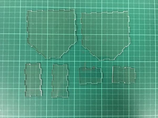
tep 4: Laser Cut the Encasing
Lastly, laser cut the encasing. Attached are the following files:
- Encasing TOP
- Encasing BOTTOM
- Encasing LARGE face (cut this file TWICE to end up with two faces)
- Encasing SIDE WITH HOLE
- Encasing SIDE WITHOUT HOLE
The file entitled Encasing FULL is just all of the above PDF files above compiled in a single page for when you have a large enough space on your acrylic sheet to accommodate the entire design.
The cutting process for this should take 10-20 minutes.
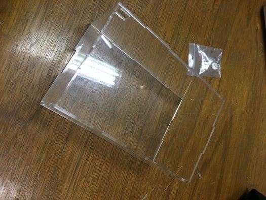
Step 5: Assemble the Food Storage
Now, carefully assemble the food storage or hopper. Take your cut acrylic and remove the paper backing.
This design is meant to be friction fit, but you may choose to add some Tamiya cement glue or glue gun to strengthen the storage bin.
Some tips for friction fitting:
- Take 2 adjacent faces (I usually start with the biggest ones) and snap their common edge in place on a flat surface first
- Slowly lift one of the faces to angle it into its proper place – like when you bend one face to form a 90 degree angle with the other face.
- Be gentle, and keep going until you have assembled the whole thing
Step 6: Assemble the Hexagonal Encasing
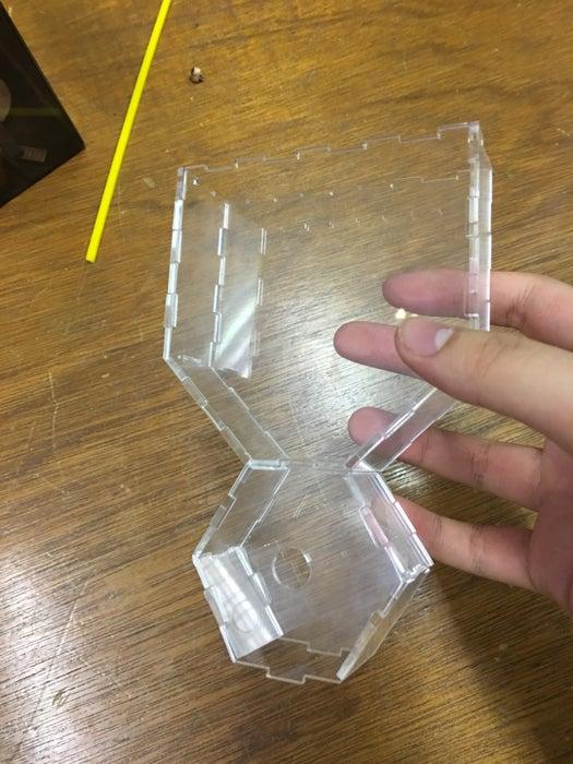
Now, do the same thing when assembling your hexagonal encasing. Start assembling the parts on the hexagonal face that has a hole. Leave the other hexagonal face for now as we still need to attach the Servo arm and the rotational arm inside the hexagonal encasing.
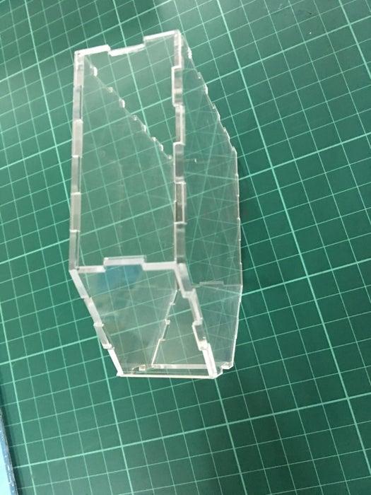
Step 7: Assemble the Encasing
Next, assemble the encasing.
To assemble the encasing:
Make sure that the hole of the BOTTOM face near one of the LARGE faces, and the hole of the SIDE WITH HOLE is nearer the opposite LARGE face. This is because the hole of the BOTTOM face should be where the food will drop out, and the hole of the SIDE WITH HOLE is for the power cable to connect to the Arduino
Do not put on of the LARGE faces yet as we still need an opening to allow us to install the food storage, hexagonal encasing, and the circuit.
Step 8: Build Your Circuit
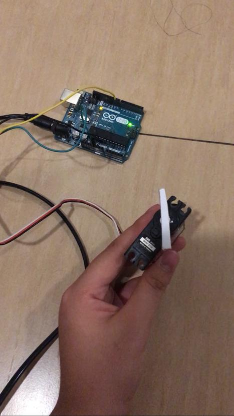
To build the circuit, you need to do the following
- Get one wire (stripped on both ends) and insert one end to port that says GND on the Arduino. This stands for ground.
- Take the other end of this wire and insert it in the female end of the black wire of your Servo.
- Get another wire and insert one end to the port that says 5V on the Arduino.
- Take the other end of this wire and insert in the female end of the red wire of your Servo.
- Lastly, get another wire and insert one end to pin 9 on the Arduino.
- Take the other end of this wire and insert it in the female end of the white wire of your Servo.
Next, make you sure you have installed the Arduino IDE. This will allow you to create and upload programs to your Arduino.
Upload SweepDos.ino to your Arduino. You may change the degrees from 90 to 60 depending on the needs of you finished rotational arm. You may also change the time of delay between rotations according to your needs.
You can now disconnect your Arduino from your computer. You can now plug then connect the AC/DC adaptor to your board to test out your circuit.
Source: Acrylic Fish Feeder