
Summary of A DIY Smart Insole to Check Your Pressure Distribution
This article details the construction of a DIY Smart Insole that monitors foot pressure distribution and motion in real-time. The system utilizes Force Sensitive Resistors (FSRs) to measure weight on specific foot areas (eversion, inversion, heel) and an accelerometer to track gait dynamics. Data is processed by an Arduino MKR1000 and transmitted via Wi-Fi to the Thinger.io platform for cloud visualization. The project emphasizes careful soldering of sensors and proper placement within the shoe sole to ensure accurate readings.
Parts used in the Smart Insole:
- Arduino MKR1000
- Interlink model 402 Force Sensitive Resistor (x3)
- OpenBuilds Wire Cable
- Resistor 10k ohm (x3)
- Power Bank
- SparkFun Triple Axis Accelerometer Breakout - ADXL345
- Soldering iron
- Solder and heat shrink
- Tape (for wires and accelerometer)
- Velcro tape
The smart insole collects foot pressure data in real-time. Through Thinger.io the information is fed into a system that visualizes the data.
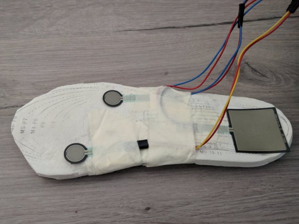
Things used in this project
Hardware components |
||||||
 |
|
× | 1 | |||
|
× | 3 | ||||
 |
|
× | 1 | |||
 |
|
× | 3 | |||
|
× | 1 | ||||
 |
|
× | 1 | |||
Software apps and online services |
||||||
 |
|
|||||
 |
|
|||||
Hand tools and fabrication machines |
||||||
 |
|
|||||
Story
Pressure measurement is already used in a variety of situations. It provides information about gait mechanics and has a wide range of applications, i.e. in clinical situations and in sports. In this project the sensors are used to gain insight about weight distribution. Real-time visualization of pressure mapping is also incorporated because it makes it much easier to understand your data.
Required hardware
- Arduino MKR1000 – Most 3.3V or 5V boards with Wi-Fi will do the job, but I wouldn’t encourage to use an ESP for this though. For some reason multiple ESP boards returned inaccurate measurements while creating this project.
- Force Sensitive Resistors (3). I used the Interlink 402 (100 N). I’ve also used one more expensive Interlink 406, but in hindsight the 402 would’ve worked too. Use more FSR’s for better accuracy.
- 10K Resistors. Change the resistor to scale your readings to be in the range you want. The higher the resistors, the bigger the increments are. Find more information on this here.
- Accelerometer, I’ve used the 16G ADXL345. Use this to measure acceleration and motion of the foot.
- A soldering iron to put it all together. Alligator clips don’t work well in a shoe for obvious reasons.
Wiring things up
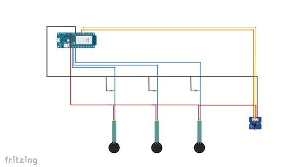
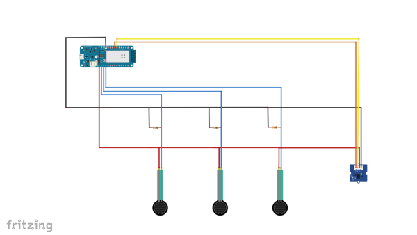
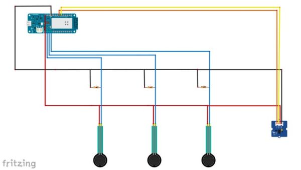 Schematics of our hardware
Some quick notes about the circuit:
FSR’s: Read this before you start soldering: be extremely cautious while soldering the wires to the FSR’s. Don’t attempt to do this if you’re not sure if you have the skills. You need to solder it very quickly or the plastic melts. Believe me, I found it out the hard way…
There is no positive or negative side on a FSR, so you don’t have to worry about that.
As I mentioned earlier, you can change the resistors to scale your readings to be in the range you prefer.
Ground/5V: As you can see, all the sensors are soldered to the 5V line and the common.
Accelerometer: You can leave the accelerometer out if you don’t need it for your project. It’s not necessary to use it if you just want to measure the pressure, but it may come in handy if you like to measure acceleration, or if you need to analyze the gait cycle. It’s not strictly necessary for this tutorial however.
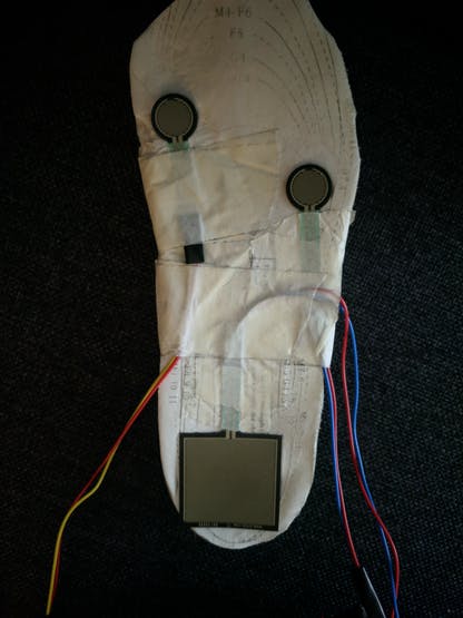
Attaching the hardware to the insole
I recommend to do this after running the code first, because if you made any soldering mistakes you’ll find it out at that point. That may save you some hassle attaching and re-attaching the hardware to the insole in case you need to resolder anything.
The FSR’s are attached to three points of the insole. The upper left FSR measures eversion, the upper right FSR measures inversion, and the FSR at the heel measures heel pressure. Finding the right spot for your FSR’s is a matter of trying. The best position to attach them is the spot where the analog value changes the most while walking.
Tape is used to hold the wires in place. If they move, it may cause interference with FSR readings. I’ve also used velcro tape at the bottom of the sole and the inside of the shoe in order to hold the insole in place.
Attach the accelerometer to the back of the heel of the shoe if you use one. I’ve used double sided tape for that.
Measuring the forces
Now we’re all set to measure the forces. Note: In the next two sections I assume familiarity with the Thinger.io library. For more information on this, I refer to the section titled “send the data through Thinger.io”.
The program has quite a long header part, including the variables that are needed to set things up, like the WiFi connection data. This part also includes the global variables, mostly arrays, used in the program. One important choice I made was to use arrays as much as possible. The idea is to use individual array elements for each FSR sensor. So in this case the arrays have a length of 3.
Don’t make it a habit to use too many global variables, because of unwanted side effects. We used them because in several cases they are necessary to send the data through Thinger.io.
The code is explained in the comments. We’ll go through the code step by step. You can download the full code below.
#define _DEBUG_ //enables us to use the Serial Monitor
#include <WiFi101.h>
#include <ThingerWifi101.h>
#include <Wire.h> //Accelerometer
#include <Adafruit_Sensor.h> //Accelerometer
#include <Adafruit_ADXL345_U.h> //Accelerometer
#include <Adafruit_NeoPixel.h>
#define USERNAME "yourUsername"
#define DEVICE_ID "yourDeviceID"
#define DEVICE_CREDENTIAL "yourDeviceCredential"
#define SSID "yourSSID"
#define SSID_PASSWORD "yourSSIDPassword"
//*FSR sensors*/
#define noFSRs 3 // Number of FSRs connected
#define FSR1 A1
#define FSR2 A2
#define FSR3 A3
float fsrVoltageArray[3];       // The analog reading converted and scaled to voltage as a floating point number
float fsrForceArray[3];         // The force in Newton
float fsrWeightInGramsArray[3]; // Weight converted to grams
int   pinArray[3]       = {FSR1, FSR2, FSR3};    // The pin ID for the three devices
float forceMaxArray[3]  = {100.0, 100.0, 100.0}; // Maximum forces supported
float million = 1000000.0; // Unit for "1/micro
float conversionToKgrams = 1.0/9.80665;
long K       = 1000;
long R       = 10*K;    // R in K Ohm
long Vcc     = 5000;    // 5V=5000mV, 3.3V = 3300 mV
float voltageMax = 0.98 * Vcc; // Maximum voltage set to 95% of Vcc. Set the force to the maximum beyond this value.
ThingerWifi101 thing(USERNAME, DEVICE_ID, DEVICE_CREDENTIAL);
Don’t panic if you don’t understand all of it yet. It’ll make more sense, once you’ve seen the rest of the code.
We want to visualize the results. For this we use the Thinger.io Wi-Fi library. This connection is set up through the following line:
ThingerWifi101 thing(USERNAME, DEVICE_ID, DEVICE_CREDENTIAL);
The input arguments are obtained via your account on Thinger.io, so you need to set this up first.
In the setup() function, the serial connection is established first. This is followed by a call to create the WiFi connection.
void setup(void) {
 Serial.begin(115200); //Start Serial Communication
 thing.add_wifi(SSID, SSID_PASSWORD); //call to set up WiFi function
}
void loop(void) {
 thing.handle();
}
Next, we define a “thing” called “pressure”. A “thing” is a key concept from the Thinger.io library. It behaves like a function, but has a special structure. It is needed to send the result data to the cloud. More details on this library can be found in section “Send the data through Thinger.io”.
The “thing” called “pressure” reads the values of the three FSR sensors and prints them on the serial console. The same values are also sent to the “out” channel. In this way, we can easily verify the raw input data.
In the “thing” with the name “voltage”, the voltage values are read and stored in a local variable called “fsrReading”. With the “map” function the value is scaled, relative to the minimum and maximum values supported, and returned into array “fsrVoltageArray”. Through the for-loop, we ensure that each FSR has its own location in this result array.
Note that all the code is put inside the setup function. Don’t put anything inside the loop (as you’re probably used to). The Thinger.io library can’t handle that…
void setup(void) {
 Serial.begin(115200); //Start Serial Communication
 thing.add_wifi(SSID, SSID_PASSWORD); //call to set up WiFi function
  /*FSR sensors*/
 thing["pressure"] >> [](pson & out) {
   out["FSR1"] = analogRead(FSR1);
   Serial.print("FSR1:");
   Serial.println(analogRead(FSR1));
   out["FSR2"] = analogRead(FSR2);
   Serial.print("FSR2:");
   Serial.println(analogRead(FSR2));
   out["FSR3"] = analogRead(FSR3);
   Serial.print("FSR3:");
   Serial.println(analogRead(FSR3));
 };
 thing["voltage"] >> [](pson & out) {
   for (int FSR = 0; FSR < noFSRs; FSR++) {
     fsrVoltageArray[FSR] = 0.0; // Reset values upon entry
     fsrForceArray[FSR]   = 0.0;
     int fsrPin   = pinArray[FSR];
     int fsrReading = analogRead(fsrPin);
     fsrVoltageArray[FSR] = (float) map(fsrReading, 0, 1023, 0, 5000); //change the 5000 to another value if you don't use a 5V device
   } //end of loop over FSR's
   out["FSR1voltage"] = fsrVoltageArray[0];
   out["FSR2voltage"] = fsrVoltageArray[1];
   out["FSR3voltage"] = fsrVoltageArray[2];
 };
void loop(void) {
 thing.handle();
  //Don't put any code here because Thinger.io won't like that.
}
After the for-loop has completed, the values are sent to the output channel “out”. Each sensor has a unique string, like “FSR1voltage”.
The “thing” called “newton” is the most complex function in this program. It converts the voltage to a force in Newtons. Again a for-loop is used to do this for each FSR.
The computation is fairly complex, because we need to distinguish several corner cases. In case the voltage value is either too small, or too large, we assign a fixed value to the force. In case the voltage is in between the cut-off values, a logarithmic function is used to compute the force. This function is chosen to reduce the slope of the curve.
Note that the formulas are only approximate. Each sensor may have a (somewhat) different curve, but for simplicity we do not distinguish this here.
The resulting value from the computations is stored into array “fsrForceArray”. Again, each FSR has its own position in this array. The three final values are sent to the “out” output channel.
The final “thing” function is called “weight”. A straightforward conversion is applied to return the force as the weight in grams.
thing["newton"] >> [](pson & out) {
   for (int FSR = 0; FSR < noFSRs; FSR++) {
        // The value of the force F as a function of the voltage V is computed as: F(V) = (Fmax/Vmax) * V
        float force_value = (forceMaxArray[FSR]/voltageMax) * fsrVoltageArray[FSR];
        // Three situations are distinguished:
       //
        // 1. If V is too close to the maximum (as defined by voltageMax), the
        //
        // 2. If the computed force F is too small, we set it to zero to avoidnoise effects.
        //
        // 3. In all other cases, we take the logarithmic value to reduce the sloop and
        if ( fsrVoltageArray[FSR] < voltageMax ) {
          // V is not too high in this branch
          if ( force_value <= 1.00 ) {
             fsrForceArray[FSR] = 0.0; // Force is too small, set it to zero
          } else {
            fsrForceArray[FSR] = log10(force_value); // Value is okay, take the log of this
          }
       } else {
          // Cap the force if the voltage is too close to Vcc (for Vcc it would be infinity)
          fsrForceArray[FSR] = log10(forceMaxArray[FSR]);
          Serial.print("Cut off activated for FSR = "); Serial.println(FSR);
       }
  } // End of loop over FSRs
     out["FSR1newton"] = fsrForceArray[0];
     out["FSR2newton"] = fsrForceArray[1];
     out["FSR3newton"] = fsrForceArray[2];
 }; //end of thing
   thing["weight"] >> [](pson & out) {
   // Straightforward computation to convert the force in Newton to the weight in grams
   for (int FSR = 0; FSR < noFSRs; FSR++) {
     fsrWeightInGramsArray[FSR] = fsrForceArray[FSR] * conversionToKgrams * 1000.0;
   }
     out["FSR1weight"] = fsrWeightInGramsArray[0];
     out["FSR2weight"] = fsrWeightInGramsArray[1];
     out["FSR3weight"] = fsrWeightInGramsArray[2];
 }; //end of thing
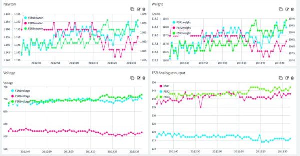
Don’t forget to set up the dashboard on Thinger.io. I assume you know how that works.
Hint: If everything works as expected, your dashboard should look similar to this:
Measuring the acceleration
This is actually much easier than measuring the pressure. We need to add some code to the header part first. We start with Including the libraries “Wire.h” (in order to communicate with the SDA and SDL pin), “Adafruit_Sensor.h”, and “Adafruit_ADXL345_U.h”. We’ll also need three new global variables, so we can measure and transfer the acceleration on the x, y and z axes
Don’t remove the libraries you’ve added earlier. You’ll need these for the connection to Thinger.io.
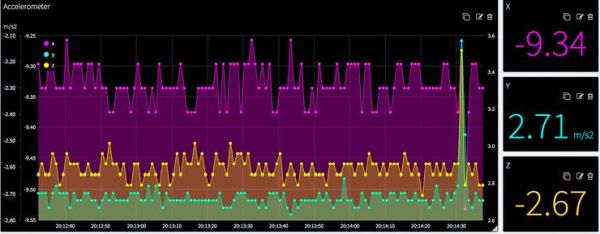
In the next block of code, we check for the accelerometer to respond. If not, nothing will happen. Otherwise, the range is defined and a “thing” called “accelerometer” is executed. This queries the device and sends the three acceleration values in the x, y, and z direction to the output “out” channel.
This partof the code is the similar to the included sample code of Adafruit (File > Examples > Adafruit ADXL345), but I left some parts out, because we don’t need them.
#include <Wire.h>
#include <Adafruit_Sensor.h>
#include <Adafruit_ADXL345_U.h>
/* Assign a unique ID to this sensor at the same time */
Adafruit_ADXL345_Unified accel = Adafruit_ADXL345_Unified(12345);
int x = 0;
int y = 0;
int z = 0;
void setup(void) {
 Serial.begin(115200);
if(!accel.begin()) {   // Initialize the sensor
  Serial.println("No ADXL345 detected");
} else {
  // Range for this sensor - If you don't know the range run the
  // displayDataRate of the example code of the ADXL345 provided by Adafruit
  accel.setRange(ADXL345_RANGE_16_G);
 thing["accelerometer"] >> [](pson& out){ // A new "thing" function for Thinger.io
     sensors_event_t event;
     accel.getEvent(&event);  // Get a new sensor event
     out["x"] = event.acceleration.x;  // Display the results (acceleration is measured in m/s^2)
     out["y"] = event.acceleration.y;
     out["z"] = event.acceleration.z;
     Serial.print("X: "); Serial.print(event.acceleration.x); Serial.print("  ");
     Serial.print("Y: "); Serial.print(event.acceleration.y); Serial.print("  ");
     Serial.print("Z: "); Serial.print(event.acceleration.z); Serial.print("  ");Serial.println("m/s^2 ");
 }; //end of thing
} //end of if/else statement
}
Hint: after running the code above, your output should look similar to the example shown below
Putting it all together
Please find the full code at the bottom of the page 🙂
Send the data through Thinger.io
This library is well documented here, but here’s some important information to make “things” (no pun intended) easier to write and use.
Thinger.io is a very extensive library. In this section we only cover the functionality needed and used in our application. The structure is as follows (note the semi-colon “;” after the closing curly brace “}”):
   thing[<string-used-as-identifier>] >> [](pson& out)
   {
       <your code>
   };
This is called a lambda function in C++. The mandatory first word to start the definition is “thing” and the entire function is also referred to as a “thing”.
The string ( for example thing[“myFirstThing”] ) gives a name to the function. Each “thing” needs to have a unique name.
The “>>” symbol indicates this “thing” has output values only. In case input is required, change this to “<<“. If both input and output is needed, the “=” symbol should be used. In our case we have output values only.
The argument “pson &out” means that our output values are sent through a data structure called “out”. The data type “pson” is very flexible and can contain various types of variables, and also supports JSON documents.
In our code we use the form "out[<unique-string-identifier>] = value" to send values to the visualization display connected with the call "ThingerWifi101 thing(USERNAME, DEVICE_ID, DEVICE_CREDENTIAL)" in the first part of the program.
As you might have noticed, there’s typically not much code inside the loop function. You’ll only need to call “thing.handle()”. You may call endpoints and stream resources in the loop part as well. All the other code is handled in the “things” you define.
The code inside the “things” is looped over continuously. It’s important to put your computations inside the “things” if your data is updated regularly, as in our case.
FAQ
Nothing happens!
Check your wires. Chances are that something broke down at this level. If nothing appears inside your Serial Monitor, check if “#define _DEBUG_” is on the first line of your code. TLS may be interferring as well. You can disable that, but be careful with this. Also check if your connection to Thinger.io is working well.
The output is not as expected
Is all the code that needs to be updated inside a “thing”? If it’s outside a “thing” it’s not updated. I’ve also found that the ESP devices don’t work well with the FSR-sensors for no apparent reason.
The output is not updated regularly
Did you add any delays to your code? Remove them 🙂 You can set the refresh rate on Thinger.io itself.
I’d prefer to have all the output in one graph
Add all the code inside a single “thing”
Well done!
I hope this tutorial has helped you to understand the basics of FSR-sensors, accelerometers and Thinger.io. Depending on what your goals are, you may customize my code. I’d love to read any suggestions to improve this code, and please don’t be shy and share your creations! If you do have any questions I’m happy to help.
Schematics
Code
-
Which microcontroller is recommended for this project?
The Arduino MKR1000 is recommended; ESP boards may return inaccurate measurements with these sensors. -
How many Force Sensitive Resistors are required?
Three FSRs are used to measure eversion, inversion, and heel pressure respectively. -
Can I use an ESP board instead of the Arduino MKR1000?
No, the author advises against using ESP boards as they returned inaccurate measurements during testing. -
What is the purpose of the 10k resistor in the circuit?
The resistor scales the readings to the desired range; higher resistors result in bigger increments. -
Is the accelerometer strictly necessary for measuring pressure?
No, it is not necessary if you only want to measure pressure, but it helps analyze the gait cycle. -
Where should the FSRs be attached on the insole?
Attach them where the analog value changes the most while walking, typically at the upper left, upper right, and heel. -
Why should code logic be placed inside a thing function rather than the loop?
The Thinger.io library cannot handle code execution outside of defined thing functions effectively. -
What happens if the voltage reading is too close to the maximum?
The force calculation caps the value to prevent infinity errors when voltage approaches Vcc.
