Summary of Custom OBD II Gauge in With OEM Look using arduino
This project details creating a custom OBD II gauge using Arduino for a Subaru BRZ (GT86, FRS), providing an OEM-like clock and diagnostic display. It features open-source code and hardware choices optimized for small form factor, stability, and ease of integration with the vehicle's diagnostics. The project uses a monochrome SPI OLED display for high visibility and leverages Sparkfun’s STN1110/ELM327 board for OBD II communication. Additional optional sensors and customization advice are provided, with full source code and discussion available on GitHub and FT86Club forums.
Parts used in the Custom OBD II Gauge Project:
- Arduino or Arduino clone (Adafruit Pro Trinket recommended)
- Sparkfun OBD II board with STN1110/ELM327 technology
- OLED monochrome SPI display (128x32 pixels, Adafruit recommended)
- OEM clock from Scion FRS (or compatible vehicle clock)
- Resistors for button setup
- Hookup wires (various types)
- Optional: Autometer sensors (oil temperature and pressure)
- Optional: Accelerometer and other pressure/temperature sensors
https://github.com/stirobot/arduinoModularTFTgaugesI built a custom OBD II (on board diagnostics version 2 http://en.wikipedia.org/wiki/On-board_diagnostics)
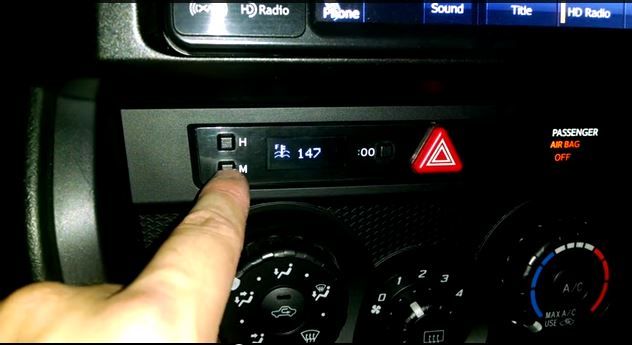
The clock in my Subaru BRZ (GT86, FRS) was a popular feature, and many people asked me to make one for them. This is how you can construct your own. My spouse is close to delivering our second son and since all the code is open source, I have no risk in sharing this.
I might eventually offer the installation as a service or sell a kit, but that won’t stop others from using the open source components for their own projects. There is really no profit to be made in this endeavor. Therefore, I prefer to distribute it among the DIY community as a whole.
I will attempt to indicate when I made modifications tailored to my vehicle model and when you may need to adjust to fit your preferences. I hope that this will enable others to expand upon the work I have completed.
The all important github link:https://github.com/stirobot/arduinoModularTFTgauges/blob/master/oledOBDgaugesSmallIrvinedLib.ino
And more generically my code is here: https://github.com/stirobot/arduinoModularTFTgauges
The car specific forum where all of this is getting discussed: http://www.ft86club.com/forums/showthread.php?p=1967204#post1967204
Step 1: What you will need to do this (parts/tools/software/etc)
Parts (generic/specific):
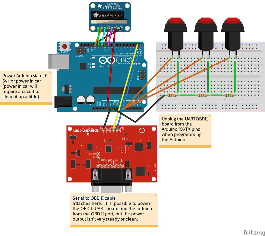
-An Arduino or Arduino clone – I specifically use the adafruit pro-trinket for its small form factor and 5v logic.https://www.adafruit.com/products/2000
Board with STN1110/ELM327 technology. I selected the Sparkfun option due to its stability, utilization of UART for communication, and reasonable price. Check it out at https://www.sparkfun.com/products/9555.
-Different varieties of hookup wire
OLED display that is monochrome and operates on SPI with a resolution of 128×32 pixels. I employed the adafruit unit. The ones from eBay might be equally effective, but I haven’t tried them yet.
– The clock provided by the original equipment manufacturer. I utilized the original equipment manufacturer clock from a Scion FRS that I purchased on ebay.
-Some resistors are needed for the button setup.
– Optional equipment includes sensors for oil temperature and pressure from Autometer, as well as an accelerometer and additional pressure and temperature sensors. I possess Arduino code which allows for the connection of analog sensors to a setup similar to this one. I will create a page dedicated to this topic on the “steps” section.
Tools:
-Soldering Iron
-Wire stripers
-Wire crimpers
-Helping hands
-scissors
-dremel tool
Code libraries used:
-Arduino ELM327 library: https://www.clusterfsck.io/blog/2014/05/23/arduino-elm327-library/ . I thrashed around with the UART
-STN1110/ELM327 circuit board. I selected the Sparkfun option due to its stability, utilization of UART for communication, and affordable price. See more details at https://www.sparkfun.com/products/9555.
I have been communicating with the OBD II board for a while now. (evident in my poorly written code for the 1.8” TFT version of this). This preserved both my project and my mental stability.
I appreciate the Adafruit libraries for the OLED screen and tutorials available at https://learn.adafruit.com/monochrome-oled-breakouts because they always offer plenty of additional resources like support, functional code, tutorials, and more that come with your purchase.
Software:
Stino plugin for Sublime Text2 brings a refreshing touch with real syntax highlighting – http://robot-will.github.io/Stino/
the dot factory is used to convert monochrome bitmaps into arrays for displaying icons on the screen (That’s how I obtained my icons)
Windows paint is used for creating icons and splash screens.
Step 2: Choosing your screen
I’ve been through several projects like this in the past and I have some advice to share on selecting a screen.
-You want the screen to fit in the OEM location with as little modification to the car as possible. I ended up measuring everything and cutting out templates on paper to see what would fit. For an old project similar to this I used a standard 16×2 character LCD. It fit perfectly in the GD Impreza’s clock location (https://code.google.com/p/robotmeter/)
-You are looking for the maximum amount of support possible when it comes to a graphics API. The adafruit products are amazing. Their TFT and OLED graphics APIs are excellent.
-You desire optimal visibility in any lighting situation. Cars use their displays in all lighting conditions, including night time, day time, and direct sunlight. OLED displays excel in this aspect. Transflective LCD’s excel in this aspect as well. Reflective and Transmissive LCD’s are not effective in any way.
– If the polarization of polarized sunglasses does not align correctly with the screen, it has the potential to diminish a great design. Experiment with different options before you start writing code.
For more detail: Custom OBD II Gauge in With OEM Look using arduino