
Summary of DIY Arduino 433MHz RF Receiver and Quad SPDT Relay Shield
This article introduces a DIY Arduino shield designed to add remote control capabilities via a 433.92MHz RF receiver and four SPDT relays. The shield supports switching up to 10A @ 250VAC for mains devices, features status LEDs, and includes terminal blocks for easy connections. It utilizes 2.54mm pitch headers for Arduino expansion and allows for custom antenna soldering to extend wireless range.
Parts used in the DIY Arduino RF Receiver and Quad SPDT Relay Shield:
- Arduino board
- 433.92Mhz RF receiver module
- Four SPDT relays
- Four LEDs for relay status indication
- Terminal blocks for device connection
- Antenna input for custom antenna soldering
- J5 to J8 connectors (2.54mm pitch, 15 mm male headers)
You are planning to use Arduino in your project but you need some kind of remote control functionality. A standalone Arduino won’t provide what you need but this DIY shield may be a good solution for you. It includes a 433.92Mhz RF receiver which lets you send commands to Arduino wirelessly and four SPDT relays which can be used for switching purposes.
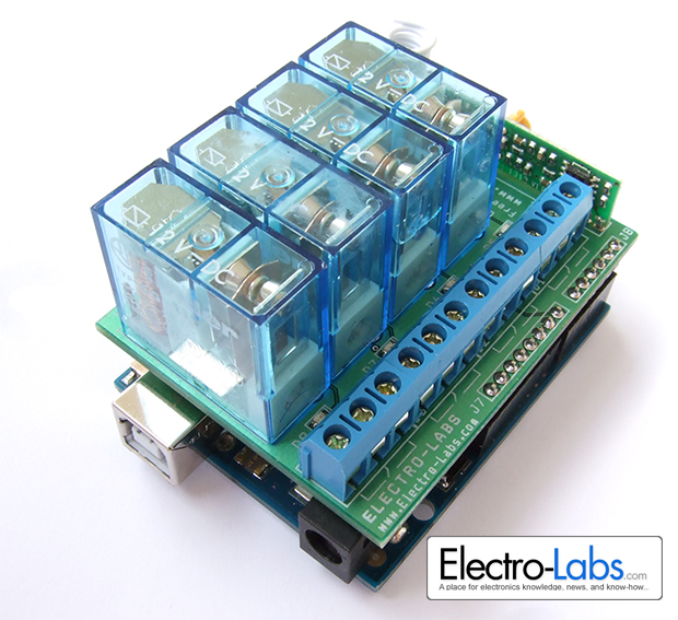
Each relay is capable of switching up to 10A @ 250VAC so they can be used to control mains powered devices. There are four LEDS indicating the status of the relays. The terminal blocks on the shield lets you easily connect the devices you will control.
The RF receiver is a module that can be found in the market easily. It is directly soldered to the shield and runs at 4800bps. The board has an antenna input which lets you solder your custom antenna to increase the wireless range.
Circuit Design
The schematic of the project is drawn in SoloCapture, the schematic editor of SoloPCB tools. SoloCapture makes the schematic drawing process very easy and fast. You can download SoloPCB tools at Fabstream.com for FREE.
You can download the SoloPCB design files of the project by using the link below.
- What is the primary function of this DIY shield?
It provides remote control functionality for Arduino using a 433.92Mhz RF receiver and four SPDT relays. - Can these relays control mains powered devices?
Yes, each relay can switch up to 10A @ 250VAC. - How does the project indicate relay status?
There are four LEDs on the board indicating the status of the relays. - What type of connectors connect the shield to the Arduino?
J5 to J8 connectors with a 2.54mm pitch and 15 mm male header length are used. - How can I increase the wireless range of the RF receiver?
You can solder a custom antenna to the antenna input on the board. - At what speed does the RF receiver module run?
The module runs at 4800bps. - Is the RF receiver module included or sold separately?
The text states it is a module found easily in the market that is directly soldered to the shield. - Where can the design files for this project be downloaded?
The SoloPCB design files can be downloaded from Fabstream.com.