Summary of Water level controller using arduino
This article describes an Arduino-based water level controller that monitors tank levels via a 16×2 LCD and automatically controls a motor. It prevents dry running by checking the sump tank and alerts users with beeps during low levels or faults. The system uses conductive probes at specific intervals to detect water presence, converting conductivity into voltage readings for the microcontroller.
Parts used in the Arduino Water Level Controller:
- Arduino board
- 16×2 LCD display
- Motor (for water pumping)
- Four aluminum wires (probes) for the main tank
- One bottom wire (reference probe)
- Analog input pins A1, A2, A3, and A4
- Resistors R6 to R9 (pull down resistors)
- +5V DC power supply
- Buzzer (for audio alerts)
- Sump tank monitoring sensors
Arduino water level controller / indicator.
This article is a about a fully functional water level controller using Arduino. The circuit displays the level of water in the tank and switches the motor ON when the water level goes below a predetermined level. The circuit automatically switches the motor OFF when the tank is full. The water level and other important data are displayed on a 16×2 LCD display. The circuit also monitors the level of water in the sump tank (source tank). If the level in side the sump tank is low, the motor will not be switched ON and this protects the motor from dry running. A beep sound is generated when the level in the sump tank is low or if there is any fault with the sensors.
Circuit diagram.
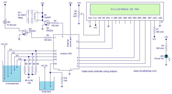
The circuit diagram of the water level controller using Arduino is shown above. Conductive method is used to measure the level. The sensor assembly consists of four aluminum wires arranged at 1/4, 1/2, 3/4 and full levels in the tank. The dry ends of these wires are connected to analog input pins A1, A2, A3 and A4 of the Arduino respectively. A fifth wire is positioned at the bottom of the tank. Resistors R6 to R9 are pull down resistors.The dry end of this wire is connected to +5V DC. When the water touches a particular probe, electrical connection is established between that probe and the +5V probe because water has slight conductivity. As a result current flows through that probe and this current is converted into a proportional voltage by the pull down resistor. Arduino reads the voltage dropped across each pull down resistor for sensing the level of water in the tank. Same method is used for measuring the level of water in the sump tank.
For more detail: Water level controller using arduino
- How does the circuit measure water levels?
The circuit uses a conductive method where four aluminum wires are placed at specific levels; when water touches a probe, it connects to a +5V reference wire, creating a current converted to voltage. - Can the system prevent the motor from dry running?
Yes, the circuit monitors the sump tank level and will not switch the motor ON if the water level inside the sump is low. - What happens when the sump tank level is low?
A beep sound is generated to alert the user, and the motor remains switched OFF to protect it. - How many probes are used in the main tank sensor assembly?
There are five wires total: four arranged at 1/4, 1/2, 3/4, and full levels, plus one positioned at the bottom of the tank. - Where are the dry ends of the main tank probes connected?
The dry ends of the four main probes are connected to analog input pins A1, A2, A3, and A4 of the Arduino respectively. - Does the system provide visual feedback on water levels?
Yes, the water level and other important data are displayed on a 16×2 LCD display. - What component generates an alert for sensor faults?
A beep sound is generated if there is any fault with the sensors or if the sump tank level is low. - How is the voltage signal created for sensing?
Current flowing through a touched probe passes through a pull down resistor, which converts the current into a proportional voltage that the Arduino reads.