Summary of Frequency counter with PIC16F628A
This article details the design of a frequency counter module using a PIC16F628A microcontroller. Unlike previous CMOS-based versions, this project utilizes a single microcontroller to drive a 6-digit multiplexed 7-segment display by employing a transistor to manage the first digit's common cathode. The system uses an internal 4MHz oscillator for processing, a 32.768Hz crystal for Timer1 timing, and measures input signals up to approximately 930kHz via Timer0.
Parts used in the Frequency Counter with PIC16F628A:
- PIC16F628A microcontroller
- Six digit 7-segment LED display (BC56-12SRWA)
- Transistor Q1
- 32768Hz external crystal oscillator
- Crystal oscillator (2x6mm recommended)
- CPU clock oscillator (Internal 4MHz)
Frequency counter with PIC16F628A
Some time ago I made an audio oscillator with frequency counter which worked very well, but I sold it, and now I am making a new one. The oscillator itself will be mostly the same and when I finish the whole project there will be a separate article. Here I will show the frequency counter module I made for the project.
The previous frequency counter was made with CMOS logic ICs, but as I already own a PIC programmer, this one is designed with PIC microcontroller. As usual I searched the web for inspiration. The original idea came from this project: LCD frequency counter. As you can see – very simple and yet elegant schematic. But I wanted to use 7-segment LED display, not LCD, so I found a second useful project: Simple 100MHz frequency counter which uses 6 digit LED display.
Combining two projects into one wasn’t very easy. First of all I wanted a PIC microcontroller to do the whole job without any additional ICs. Also I wanted to use the the familiar 16F628A, but because one of the portA pins (RA5) can be used only as input I was short of outputs to do the job. Driving 6 digit 7-segment multiplexed display requires 7 + 6 = 13 outputs. The 16F628A has 16 IO pins, two of which are used for the crystal oscillator, one is for the signal input and other one can be used only for input, that leaves us with only 12 useful IO pins. The solution was to drive one of the common cathodes with a transistor, which opens when all other digits are switched off.
Here is the final schematic:
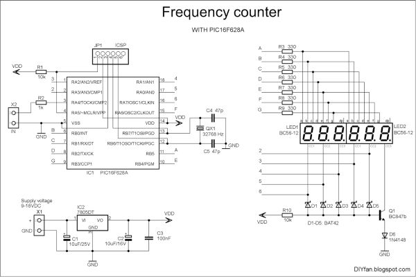
7-segment displays used here are 3 digit multiplexed common cathode type (BC56-12SRWA). Digits 2..5 are switched on when respective pins are set low. When all these pins are high, the transistor Q1 opens and switches on the first digit. The current for each segment is about 6-7mA.
I must mention that pins connected to common cathodes theoretically may sink up to 50mA if all segments are light up (7x7mA). This is way above max specifications of the microcontroller. But as every digit is switched on for very brief moment I think it is safe. The whole schematic consumes around 30-40mA in average and the microcontroller is not heating at all, so everything seems OK.
The microcontroller uses its internal 4MHz oscillator for the CPU clock. Timer1 uses external crystal oscillator with frequency 32768Hz for setting the 1 second time interval. Timer0 is used to count the input signal at pin RA4. And finally, Timer2 is used for cycling and refreshing the digits.
As the input signal will be 5Vpp square wave there isn’t any preamp or buffer in the front.
The counter can measure up to 920-930kHz which is more than enough for my project. The reason why it can’t go higher is because driving all these digits consumes lots of CPU cycles. I suppose, the program code can be optimized or even written in assembler and then the counter can reach 999999 Hz.
The crystals for 32768Hz are sold in two sizes : 2x6mm and 3x8mm. I recommend 2x6mm because it fits perfectly below the left display. The other size also can be used but it will lift a little the left display.
For more detail: Frequency counter with PIC16F628A
- Why was a transistor added to the circuit?
A transistor is used to drive one of the common cathodes because the PIC16F628A lacks enough output pins to directly switch all six digits. - What is the maximum frequency this counter can measure?
The counter can measure up to 920-930kHz due to the CPU cycles consumed by driving the display digits. - Which timer is used to count the input signal?
Timer0 is used to count the input signal located at pin RA4. - How does the microcontroller generate the one-second time interval?
Timer1 uses an external crystal oscillator with a frequency of 32768Hz to set the 1 second time interval. - What size crystal is recommended for the 32768Hz component?
The 2x6mm size is recommended because it fits perfectly below the left display. - Is there a preamp or buffer in the front end of the circuit?
No, there is no preamp or buffer because the input signal is a 5Vpp square wave. - Can the measurement range be increased beyond 930kHz?
Yes, the range could potentially reach 999999 Hz if the program code is optimized or written in assembler. - How much current does each segment draw?
The current for each segment is about 6-7mA.