
Summary of AppNote: How to Use the MAX17501 and MAX17502 for Negative Output Voltage Applications
This article explains using MAX17501 and MAX17502 synchronous step-down converters configured as buck-boosts to generate negative output voltages (example: −15V) from positive input rails, for industrial analog supplies. It covers design limits (VIN_MAX + |VOUT| ≤ 60V), minimum VIN (>4.5V), and duty-ratio calculation while highlighting these devices’ efficiency and thermal advantages.
Parts used in the Negative Output Voltage Application:
- MAX17501 synchronous step-down converter
- MAX17502 synchronous step-down converter
- Inductor (value per design to support buck-boost configuration)
- Input capacitors (suitable for VIN range)
- Output capacitors (for negative output filtering)
- Power switches internal to MAX17501/MAX17502 (integrated)
- PCB and connections rated for up to 60V
Abstract: This article shows how to produce negative output voltages from positive input voltages using the MAX17501 and MAX17502 synchronous step-down converters.
Introduction
Industrial control equipment such as programmable logic controllers, I/O modules, mass flow controllers, and various other sensors and supporting systems use analog components like amplifiers and multiplexers that operate on negative supply voltage. Typically operating at ±12V, ±18V or other variations, these voltages are generated from a 24V DC bus. Maxim’s portfolio of high-voltage synchronous buck regulators offer 50% lower power loss allowing customers to operate their equipment 50% cooler. In this application note, we discuss techniques to use these synchronous buck regulators to generate negative voltages.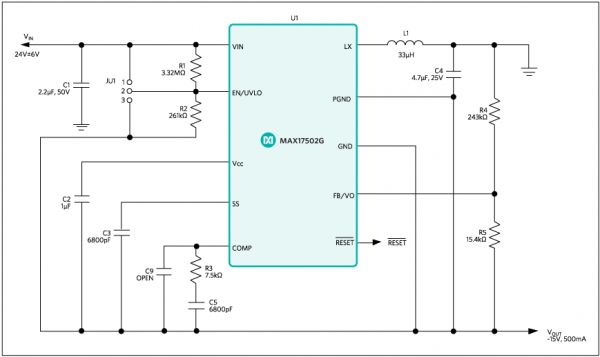
Design Considerations
Synchronous buck converters can be configured to work in a buck-boost topology to produce negative output voltage from positive input voltage. This application note explains how the MAX17501 and MAX17502 synchronous step-down converters can be used to generate negative output voltage from positive input voltage. A -15V output voltage application is used to demonstrate the principle.
Table 1. Negative Output Voltage Power-Supply Requirements.
The sum of the maximum operating input voltage for the negative output application and the absolute value of the output voltage should not exceed the maximum operating voltage (60V) of the MAX17501 and MAX17502, as expressed by the following equation:
VIN_MAX + |VOUT| ≤ 60V
Therefore, for -15V output voltage, maximum operating input voltage can be as high as 45V. The minimum operating input voltage for the negative output voltage application should be greater than 4.5V.
Calculating Duty Ratio
The expression for the duty ratio of the negative output power supply is shown below; ignoring the losses associated with the power switches and the inductor DC resistance:
For more detail: AppNote: How to Use the MAX17501 and MAX17502 for Negative Output Voltage Applications
- How can I generate a negative output voltage from a positive input using these parts?
Configure the MAX17501 or MAX17502 synchronous buck converter in a buck-boost topology to produce the negative output as shown in the application note. - What is the maximum allowed relationship between VIN and the negative output?
The sum of the maximum operating input voltage and the absolute value of the output voltage must be less than or equal to 60V (VIN_MAX + |VOUT| ≤ 60V). - What is the minimum input voltage for the negative output application?
The minimum operating input voltage should be greater than 4.5V. - Can I produce −15V from a 24V bus with these devices?
Yes; for −15V output the maximum operating input voltage can be as high as 45V, so 24V is within the allowed range. - Which devices are demonstrated for this negative output technique?
The application note demonstrates using the MAX17501 and MAX17502 synchronous step-down converters. - Does the duty ratio account for switch and inductor losses in the article?
The duty-ratio expression shown ignores losses from the power switches and the inductor DC resistance. - Why use these Maxim high-voltage synchronous buck regulators for negative outputs?
They offer lower power loss and allow equipment to operate cooler while supporting high-voltage operation for negative-output applications.
