Summary of Mastering I2C: Interfacing Arduino Boards for Seamless Communication
Summary: This article demonstrates three I2C communication scenarios between two Arduino boards: Master Transmitter → Slave Receiver, Master Receiver ← Slave Transmitter, and bidirectional Master ↔ Slave. It provides wiring guidance, Arduino Wire.h code for master and slave roles, use-case explanations, simulation references (TinkerCAD), and testing videos to show practical implementations of reading inputs on one board and controlling outputs on the other via I2C.
Parts used in the Arduino I2C Communication Between Two Arduino Boards:
- Arduino Uno (two boards)
- Potentiometer
- LED
- Resistor for LED (appropriate value)
- 4-DIP switches
- Jumper wires
- Breadboard
- I2C pull-up resistors (if not using internal pull-ups)
In this project, we will establish I2C communication between two Arduino boards. Additionally, we will revisit some fundamentals of Arduino I2C communication, serving as a concise recap of what we’ve previously covered in detail in an earlier Arduino I2C Tutorial. We will explore all three potential scenarios for I2C communication and develop three distinct Arduino projects to encompass each one:
1. I2C Master Transmitter communicating with Slave Receiver
2. I2C Master Receiver receiving from Slave Transmitter
3. I2C Master Transmitting and Receiving bidirectionally with Slave Receiving and Transmitting
We will execute these I2C communication projects between two Arduino boards both in simulation and real-life environments to assess their behavior. Without further delay, let’s delve into the exploration!
I2C Communication Between Two Arduino Boards
In an I2C setup, whether a device operates as a Master or Slave, and whether it functions as a transmitter or receiver, is determined by the system designer and programmer. When dealing with just two Arduino boards as I2C devices, the communication pattern becomes one-to-one, forming a Single-Master Single-Slave I2C bus.
Consequently, communication between the two Arduino boards can occur in three possible configurations:
1. Master (Tx) → Slave (Rx)
2. Master (Rx) ← Slave (Tx)
3. Master (TxRx) ↔︎ Slave (RxTx)
The choice among these configurations depends on the specific requirements of your application. Your selection will dictate the most appropriate form of communication between the Arduino boards.
Subsequently, we will demonstrate the implementation of each of these three forms of I2C communication between the two Arduino boards mentioned earlier. A brief use case will accompany each communication type, aiding in making informed design decisions for future projects.
Before proceeding with the examples, it is essential to familiarize yourself with the basics of Arduino I2C communication and the utilization of the Wire.h library functions. This knowledge serves as a prerequisite for seamlessly executing the example projects discussed herein.
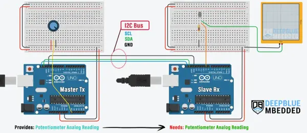
Two Arduino I2C Communication (Master Tx Slave Rx)
In this demonstration, we’ll create a project where two Arduino Boards communicate via I2C (TWI). One Arduino will serve as an I2C master transmitter, responsible for reading an analog input from a potentiometer and transmitting it to the I2C Slave Arduino board.
The second Arduino will operate as an I2C slave receiver, tasked with receiving data from the master device and utilizing it to regulate a PWM output, such as an LED. This setup establishes a unidirectional communication flow from the Arduino acting as the I2C Master Transmitter to the one functioning as the I2C Slave Receiver.
Use Case (Scenario)
This configuration of I2C communication can prove highly beneficial in various scenarios. For instance, if your Arduino board is already utilizing most of its IO pins for driving outputs such as motors or LEDs, it’s prudent to delegate the task of receiving user inputs, like button presses or potentiometer adjustments, to another board.
In this setup, the I2C slave receiver device relies on information transmitted by the master device, which reads the user inputs and forwards them to the slave receiver.
Consider a scenario where the Arduino board has exhausted its analog input channels, necessitating the connection of a potentiometer to regulate the brightness of an LED controlled via PWM. While alternatives like analog switches or external ADCs could resolve the issue, we’ll address it through I2C communication with a separate Arduino board.
To tackle this situation, designate the Arduino board requiring additional ADC inputs as an I2C slave receiver. Then, connect another Arduino board to the I2C bus, serving as a master transmitter responsible for reading the potentiometer input and transmitting the results to the slave receiver.
This example project will demonstrate precisely this solution.
Wiring
Below is the schematic diagram illustrating the connections for this example, illustrating how to link the LED output and the potentiometer analog input on both Arduino boards (I2C Master Tx & I2C Slave Rx).
Arduino I2C Master Tx Board Code
Here is the complete code listing for the Arduino I2C Master Transmitter Board.
Arduino I2C Slave Rx Board Code
Here is the complete code listing for the Arduino I2C Slave Receiver Board.
Master Code Explanation
To begin, it is imperative to incorporate the Arduino Wire.h library to enable the utilization of the I2C communication module. Additionally, we must establish a variable designated to store the analog potentiometer reading, specifically the 10-Bit ADC result.
setup()
in the setup() function, we’ll initialize the I2C module in master mode (no address is needed).
|
Wire.begin(); // Initialize I2C (Master Mode: address is optional)
|
loop()
Within the loop() function, we will continuously retrieve the analog potentiometer value, reduce it to an 8-bit range (1 byte), and transmit it via I2C to the slave device with the address set to 0x55. Subsequently, we will conclude the I2C transaction. This sequence will iterate ten times per second, facilitated by a delay of 100 milliseconds.
Slave Code Explanation
Initially, we must incorporate the Arduino Wire.h library to facilitate the utilization of the I2C communication module. Additionally, we need to specify the output PWM pin for the LED and define a variable to store the received data (byte) from the master Arduino board.
I2C_RxHandler()
This function serves as the event handler for receiving data over the I2C bus. It is invoked automatically whenever the device receives data. Within this function, we extract the incoming data byte and store it in a global variable. Subsequently, this stored value is utilized by the main function to configure the duty cycle of the PWM output.
setup()
Within the setup() function, we’ll set the LED output pin mode and initialize the I2C module in slave mode, setting the address to 85 (equivalent to 0x55 in hexadecimal). Additionally, we’ll assign the event handler function to the I2C onReceive event.
loop()
in the loop() function, we’ll apply the received duty cycle value to the PWM LED output.
|
analogWrite(LED_PIN, RxByte);
|
That concludes the project!
You can evaluate the code example for this project using any accessible Arduino simulation environment. Below, I will present the simulation outcomes for this project on TinkerCAD.
TinkerCAD Simulation
Below is the simulation outcome for this project conducted on the TinkerCAD simulator. You have the option to either run it as it stands or duplicate it, incorporate your own code, and commence the simulation to observe its behavior.
You can check this simulation project on TinkerCAD using this link.
Testing Results
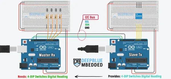
Two Arduino I2C Communication (Master Rx Slave Tx)
In this project example, we aim to enable serial communication between two Arduino boards via I2C (TWI) communication. One Arduino board will assume the role of an I2C slave transmitter, tasked with reading data from 4-DIP switches (digital inputs) and transmitting it to the I2C master receiver Arduino board.
Conversely, the other Arduino board will serve as an I2C master receiver. Its responsibility will be to receive the data transmitted by the slave device and utilize it to control a set of output LEDs. This setup constitutes a unidirectional communication flow from the Arduino I2C master receiver to the Arduino I2C slave transmitter.
Use Case (Scenario)
This particular I2C communication setup can prove immensely beneficial in various scenarios. For instance, when an Arduino board is heavily utilizing its IO pins for driving outputs such as motors or LEDs, there arises a need for another board dedicated to processing user inputs from devices like buttons, potentiometers, or joysticks, and transmitting these readings to the output-driving Arduino board.
In this configuration, the I2C master receiver device seeks information from the slave transmitter, which is responsible for reading user inputs and relaying them to the I2C master receiver device.
For example, suppose our Arduino board has exhausted its digital IO pins, and we require connectivity for 4 DIP switches to control the On/Off state of 4 LEDs. While solutions like multiplexers or IO expanders could address this issue, an alternative approach involves leveraging I2C communication with another Arduino board possessing available IO pins.
The resolution to this scenario involves configuring the Arduino board in need of additional digital input pins as an I2C master receiver. Simultaneously, another Arduino board is connected to the I2C bus, serving as a slave transmitter responsible for reading digital inputs and relaying the results to the master receiver.
This example project illustrates precisely how to implement this solution.
Wiring
Below is the schematic diagram illustrating the setup for this example, detailing the connection of the output LEDs and the 4-DIP switches input on both Arduino boards (I2C Master Rx & I2C Slave Tx).
Arduino I2C Master Rx Board Code
Here is the complete code listing for the Arduino I2C Master Receiver Board.
|
1
2
3
4
5
6
7
8
9
10
11
12
13
14
15
16
17
18
19
20
21
22
23
24
25
26
27
28
29
30
31
32
33
|
/*
* LAB Name: Arduino I2C Master(Rx)
* Author: Khaled Magdy
* For More Info Visit: www.DeepBlueMbedded.com
*/
#include <Wire.h>
#define LED0_PIN 4
#define LED1_PIN 5
#define LED2_PIN 6
#define LED3_PIN 7
byte RxByte;
void setup() {
Wire.begin(); // Initialize I2C (Master Mode: address is optional)
pinMode(LED0_PIN, OUTPUT);
pinMode(LED1_PIN, OUTPUT);
pinMode(LED2_PIN, OUTPUT);
pinMode(LED3_PIN, OUTPUT);
}
void loop() {
Wire.requestFrom(0x55, 1); // Request From Slave @ 0x55, Data Length = 1Byte
while(Wire.available()) { // Read Received Datat From Slave Device
RxByte = Wire.read();
}
digitalWrite(LED0_PIN, (RxByte&0x01));
digitalWrite(LED1_PIN, (RxByte&0x02));
digitalWrite(LED2_PIN, (RxByte&0x04));
digitalWrite(LED3_PIN, (RxByte&0x08));
delay(100);
}
|
Arduino I2C Slave Tx Board Code
Here is the complete code listing for the Arduino I2C Slave Transmitter Board.
|
1
2
3
4
5
6
7
8
9
10
11
12
13
14
15
16
17
18
19
20
21
22
23
24
25
26
27
28
29
30
31
32
33
34
35
36
37
|
/*
* LAB Name: Arduino I2C Slave(Tx)
* Author: Khaled Magdy
* For More Info Visit: www.DeepBlueMbedded.com
*/
#include <Wire.h>
#define BTN0_PIN 4
#define BTN1_PIN 5
#define BTN2_PIN 6
#define BTN3_PIN 7
byte TxByte = 0;
void I2C_TxHandler(void)
{
Wire.write(TxByte);
}
void setup() {
pinMode(BTN0_PIN, INPUT_PULLUP);
pinMode(BTN1_PIN, INPUT_PULLUP);
pinMode(BTN2_PIN, INPUT_PULLUP);
pinMode(BTN3_PIN, INPUT_PULLUP);
Wire.begin(0x55); // Initialize I2C (Slave Mode: address=0x55 )
Wire.onRequest(I2C_TxHandler);
}
void loop() {
byte BtnsData = 0;
BtnsData |= digitalRead(BTN0_PIN) << 0;
BtnsData |= digitalRead(BTN1_PIN) << 1;
BtnsData |= digitalRead(BTN2_PIN) << 2;
BtnsData |= digitalRead(BTN3_PIN) << 3;
TxByte = BtnsData;
delay(10);
}
|
Master Code Explanation
First of all, we need to include the Arduino Wire.h library to use the I2C communication module, define the IO pins for output LEDs, and define a variable to hold the received byte from the I2C slave device that holds the 4-DIP switches states.
|
1
2
3
4
5
6
7
8
|
#include <Wire.h>
#define LED0_PIN 4
#define LED1_PIN 5
#define LED2_PIN 6
#define LED3_PIN 7
byte RxByte;
|
setup()
in the setup() function, we’ll initialize the I2C module in master mode (no address is needed), and we’ll initialize the IO pins used for LEDs as output pins.
|
1
2
3
4
5
|
Wire.begin(); // Initialize I2C (Master Mode: address is optional)
pinMode(LED0_PIN, OUTPUT);
pinMode(LED1_PIN, OUTPUT);
pinMode(LED2_PIN, OUTPUT);
pinMode(LED3_PIN, OUTPUT);
|
loop()
in the loop() function, we’ll request the 4-DIP switches’ states from the I2C slave device @ the address 0x55. As an I2C master device, we’ll initiate the I2C transaction with the slave device by doing this. After getting the response, we’ll store it in the global RxByte variable.
|
1
2
3
4
|
Wire.requestFrom(0x55, 1); // Request From Slave @ 0x55, Data Length = 1Byte
while(Wire.available()) { // Read Received Datat From Slave Device
RxByte = Wire.read();
}
|
Next, we’ll parse out the individual bits inside the received byte that represents the 4-DIP switches states and control the output LEDs accordingly.
|
1
2
3
4
|
digitalWrite(LED0_PIN, (RxByte&0x01));
digitalWrite(LED1_PIN, (RxByte&0x02));
digitalWrite(LED2_PIN, (RxByte&0x04));
digitalWrite(LED3_PIN, (RxByte&0x08));
|
Slave Code Explanation
First of all, we need to include the Arduino Wire.h library to use the I2C communication module, define the digital input pins for the DIP switches, and define a variable to send the switches’ state data (byte) to the master Arduino board.
|
1
2
3
4
5
6
7
8
|
#include <Wire.h>
#define BTN0_PIN 4
#define BTN1_PIN 5
#define BTN2_PIN 6
#define BTN3_PIN 7
byte TxByte = 0;
|
I2C_TxHandler()
This is the I2C transmit event handler function which is automatically called whenever the device receives a data request from an I2C master device over the I2C bus. In which, we’ll send out the DIP switches’ states ( TxByte) variable.
|
1
2
3
4
|
void I2C_TxHandler(void)
{
Wire.write(TxByte);
}
|
setup()
in the setup() function, we’ll initialize the digital input pins, and initialize the I2C module in slave mode with ( address=85 or 0x55). We’ll also assign the event handler function to the I2C onRequest event.
|
1
2
3
4
5
6
|
pinMode(BTN0_PIN, INPUT_PULLUP);
pinMode(BTN1_PIN, INPUT_PULLUP);
pinMode(BTN2_PIN, INPUT_PULLUP);
pinMode(BTN3_PIN, INPUT_PULLUP);
Wire.begin(0x55); // Initialize I2C (Slave Mode: address=0x55 )
Wire.onRequest(I2C_TxHandler);
|
loop()
in the loop() function, we’ll read the digital input pins (DIP switches’ states) and save them into the TxByte global variable which will be sent to the master I2C Arduino board whenever it requests it.
|
1
2
3
4
5
6
|
byte BtnsData = 0;
BtnsData |= digitalRead(BTN0_PIN) << 0;
BtnsData |= digitalRead(BTN1_PIN) << 1;
BtnsData |= digitalRead(BTN2_PIN) << 2;
BtnsData |= digitalRead(BTN3_PIN) << 3;
TxByte = BtnsData;
|
And that’s it!
We can test this project’s code example using any available Arduino simulator environment. Here I’ll show you the simulation results for this project on TinkerCAD.
- What are the three I2C communication configurations between two Arduinos?
Master Transmitter → Slave Receiver, Master Receiver ← Slave Transmitter, and bidirectional Master Transmitting and Receiving ↔ Slave Receiving and Transmitting. - How does the Master Tx Slave Rx example send analog data?
The master reads a potentiometer via analogRead, shifts the 10-bit value to 8-bit, and sends it with Wire.beginTransmission and Wire.write to the slave address 0x55. - Can a slave Arduino control PWM output based on received I2C data?
Yes, the slave receives a byte via onReceive handler and uses analogWrite to set PWM duty cycle for an LED. - How does the Master Rx Slave Tx example obtain switch states?
The master requests one byte from the slave using Wire.requestFrom, reads the byte, and maps its bits to LEDs with digitalWrite. - How does the slave transmitter provide DIP switch states to the master?
The slave reads DIP switch inputs, packs them into a TxByte variable, and sends it when the master requests via the onRequest handler using Wire.write. - What I2C address is used in the examples?
Both examples use the slave address 0x55 (decimal 85). - Do these examples require the Wire.h library?
Yes, all examples include the Arduino Wire.h library to use the I2C functions. - What is a suggested update rate for the Master Tx example?
The master loops with a delay(100) resulting in about ten transmissions per second.