Summary of Arduino Frequency Counter Tutorial for Electronics Enthusiasts
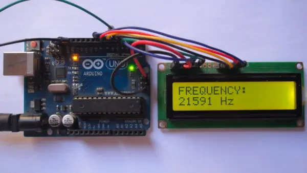
This guide details building a frequency counter using an Arduino UNO to measure 5V PWM signal frequencies. The device displays results on a 1602 LCD screen by counting pulses over one second. It utilizes the FreqCount library with Timer/Counter modules for accurate measurement, connecting the input signal to digital pin 5 and configuring the LCD via specific pin mappings.
Parts used in the Arduino Frequency Counter:
- Arduino UNO board (Atmega328P)
- 16×2 LCD screen
- 330 ohm resistor
- 10k ohm potentiometer
- Breadboard
- Jumper wires
- FreqCount library
In this guide, learn to construct a frequency counter device utilizing an Arduino UNO board. This device showcases signal frequency values on a 1602 LCD screen. It is designed specifically to measure the frequency of PWM signals that have a peak voltage of 5V.
Hardware Required:
Sure, here’s a rephrased list of the components needed to complete this project:
– Atmega328P datasheet (for Arduino UNO board)
– 16×2 LCD screen
– 330 ohm resistor
– Potentiometer (10k ohm variable resistor)
– Breadboard
– Jumper wires
Arduino frequency counter circuit:
The following details the circuit diagram for the project.
Utilizing a 16×2 LCD screen with 2 rows and 16 columns, it serves to exhibit the frequency and period values of the input voltage. Here’s the pin mapping configuration:
– RS connects to Arduino digital pin 2
– E connects to Arduino digital pin 3
– D4 connects to Arduino digital pin 4
– D5 connects to Arduino digital pin 6
– D6 connects to Arduino digital pin 7
– D7 connects to Arduino digital pin 8
– VSS, RW, D0, D1, D2, D3, and K link to Arduino GND
– VEE connects to the output of the 10k ohm variable resistor (or potentiometer)
– VDD links to Arduino 5V
– A connects to Arduino 5V through a 330 ohm resistor
The VEE pin regulates the LCD contrast, while A (anode) and K (cathode) designate the back light LED pins.
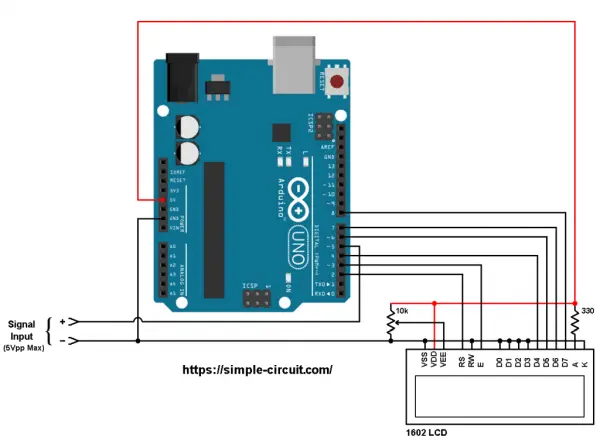
The PWM signal comprises two pins, designated as positive (+) and negative (-), and they are linked to the circuit as demonstrated earlier.
The positive terminal links to Arduino’s digital pin 5, while the negative terminal connects to the Arduino GND pin.
Arduino frequency counter code
The Arduino code provided necessitates a supporting library, namely FreqCount, to facilitate the project process. This library can be acquired through the Arduino library manager (accessible via “Manage Libraries…”), or alternatively, it can be installed manually by obtaining and installing its zip file. Below is the download link for the Arduino FreqCount library:
Direct link to Arduino FreqCount library
The FreqCount library utilizes the Timer/Counter1 module to tally the number of pulses within a set duration. For this specified duration, the Timer/Counter2 module is employed.
Full Arduino code:
- What is the purpose of this project?
The project constructs a frequency counter device that measures PWM signals with a 5V peak voltage and displays values on a 1602 LCD. - How does the circuit display frequency data?
The 16×2 LCD screen exhibits the frequency and period values of the input voltage. - Which pins connect the LCD control lines to the Arduino?
RS connects to pin 2, E to pin 3, D4 to pin 4, D5 to pin 6, D6 to pin 7, and D7 to pin 8. - How is the LCD contrast regulated?
The VEE pin regulates the LCD contrast and connects to the output of the 10k ohm variable resistor. - Where does the positive terminal of the PWM signal connect?
The positive terminal links to Arduino digital pin 5. - What duration does the timer use for counting pulses?
The FreqCount library initializes with a time basis of 1000ms, meaning it counts pulses for one second. - Which library is required to facilitate the project?
The project requires the FreqCount library to tally pulses using the Timer/Counter1 module. - Can the library be installed manually?
Yes, the library can be acquired through the Arduino library manager or installed manually by obtaining its zip file.