Summary of LANp – A DIY Arduino network controllable RGB lamp made from scanner parts!
This article details the creation of LANp, a DIY Arduino-based network-controllable RGB lamp repurposed from an old Canon scanner LED. The project uses an Ethernet shield to host a web server, allowing real-time color control via a JavaScript color picker. It highlights the process of soldering wires to the scanner's LED pads and integrating it with an SD card for file hosting.
Parts used in the LANp Project:
- 1x Arduino
- 1x Arduino Ethernet/SD Shield
- 1x Micro-SDHC Card
- 1x Scanner LED RGB (QK1-4761 from Canon PIXMA MP620)
- Various jumper wires
This is something we have really been meaning to write up. A few weeks ago we ripped out an RGB LED from an old Canon Scanner that was laying around and going to waste. Since then we’ve been playing around with the RGB LED element and decided to put it to good use.
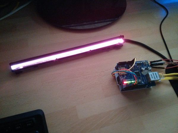
We have come up with LANp – This is an Arduino and Ethernet Shield that controls an RGB LED colour real-time with a Javascript colour picker.
Take a look below for the YouTube video of this working at the bottom of the page.
What’s in it?
- 1x Arduino
- 1x Arduino Ethernet/SD Shield
- 1x Micro-SDHC Card
- 1x Scanner LED RGB
- Various jumper wires
This webserver code is based on our previous article, located just here which shows how to set up an SD Card based web server and serve files over a network, with support for AJAX requests.
The LED Scanner bar we have is an QK1-4761 from a Canon PIXMA MP620 – At the time of writing this post there are a few listed on eBay for around £7.
We started by soldering wires on to the pads of the scanner LED. See the photo below, you may have to do some experimenting to find out which is which, but normally there is an R G B and +v pin. This LED operates at 5v (that doesn’t mean yours will though!)
As you can see on the photo to the right; we just soldered wire directly to 4 of the 5 pads – The bottom one isn’t used and the next are R G B +5v going upwards.
Make sure that none of the wires, or soldered joints are touching each other as this will skew the colour of the LED dramatically. It may be worth taping this up after soldering to avoid the wires touching when you’re moving the LED around.
For more detail: LANp – A DIY Arduino network controllable RGB lamp made from scanner parts!
- What is the LANp project?
LANp is an Arduino and Ethernet Shield that controls an RGB LED colour real-time with a Javascript colour picker. - Where does the RGB LED come from?
The LED is a QK1-4761 taken from a Canon PIXMA MP620 scanner. - How do you connect the LED to the circuit?
You must solder wires directly onto the pads of the scanner LED. - Which pins are used on the scanner LED?
The R, G, B, and +5v pins are used, while the bottom pad is not used. - At what voltage does this specific LED operate?
This LED operates at 5v, though the author notes others may differ. - Can the web server support AJAX requests?
Yes, the webserver code supports AJAX requests as shown in their previous article. - What is the best way to prevent color skewing?
Ensure that none of the wires or soldered joints are touching each other. - Is there a video demonstration available?
Yes, a YouTube video of the project working is located at the bottom of the page.