
Summary of Arduino LED Cube Spectrum Analyzer
This project builds a small add-on PCB using an MSGEQ7 spectrum analyzer to drive a Freetronics 4x4x4 RGB LED cube. The circuit analyzes audio input across seven frequency bands and maps them to the cube's vertical columns, displaying visualizations on four horizontal planes by rotating the view 45 degrees. It requires basic knowledge of the MSGEQ7 IC and the LED cube kit, utilizing an Arduino Leonardo-compatible board embedded in the cube.
Parts used in the Arduino LED Cube Spectrum Analyzer:
- MSGEQ7 spectrum analyzer IC (two recommended)
- Matching IC sockets for MSGEQ7
- Stripboard or Veroboard
- Freetronics RGB LED cube kit
- Arduino Leonardo-compatible microcontroller (built into cube PCB)
- 1000 pF capacitor
- Audio extension lead or shielded cable for input/output
- Powered speakers or headphones
- Cube library for Arduino
In this project we’ll create a small add-on PCB containing the a MSGEQ7 spectrum analyzer circuit and show how it can drive the RGB LED cube kit from Freetronics. This allows the cube to display the seven bands over four horizontal planes.
There is a small amount of assumed knowledge for this project – To save repeating myself, please familiarise yourself with the MSGEQ7 spectrum analyzer IC tutorial in Chapter 48 of our Arduino tutorials. And learn more about the LED cube from our review and the product page.
The circuit
You can get the bare MSGEQ7 ICs from Sparkfun and the other usual suspects. It never hurts to have a spare one, so order two and matching IC sockets. Finally you should be able to translate a simple circuit to prototyping board.
Step 1: The circuit
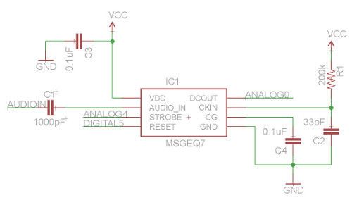
The LED cube already has an Arduino Leonardo-compatible built in to the main PCB, so all you need to do is build a small circuit that contains the spectrum analyzer which connects to the I/O pins on the cube PCB and also has audio input and output connections. First, consider the schematic in this step.
For the purposes of this project our spectrum analyzer will only display the results from one channel of audio – if you want stereo, you’ll need two! And note that the strobe, reset and DCOUT pins on the MSGEQ7 are labelled with the connections to the cube PCB. Furthermore the pinouts for the MSGEQ7 don’t match the physical reality, so compare them against the pinouts in the second image.
The circuit itself will be quite small and fit on a small amount of stripboard or Veroboard. There is plenty of room underneath the cube to fit the circuit if so desired.
Step 2: Wiring it up
With a few moments you should be able to trace out your circuit to match the board type you have, remember to double-check before soldering. You will also need to connect the audio in point after the 1000 pF capacitor to a source of audio, and also pass it through so you can connect powered speakers, headphones, etc.
One method of doing so would be to cut up a male-female audio extension lead, and connect the shield to the GND of the circuit, and the signal line to the audio input on the circuit. Or if you have the parts handy and some shielded cable, just make your own input and output leads as shown in the image for this step.
Be sure to test for shorts between the signal and shield before soldering to the circuit board. When finished, you should have something neat that you can hide under the cube or elsewhere. Double-check your soldering for shorts and your board plan, then fit to the cube along with the audio source and speakers (etc.).
Step 3: The Arduino sketch – part one
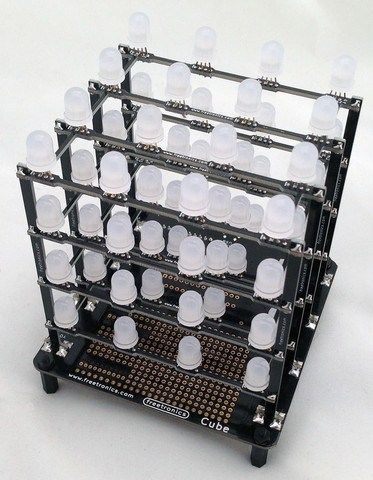
The sketch has two main functions – the first is to capture the levels from the MSGEQ7 and put the values for each frequency band into an array, and the second function is to turn on LEDs that represent the level for each band. If you’ve been paying attention you may be wondering how we can represent seven frequency bands with a 4x4x4 LED cube. Simple – by rotating the cube 45 degrees you can see seven vertical columns of LEDs (see the image of the cube with the numbered columns).
So when looking from the angle as shown above, you have seven vertical columns, each with four levels of LEDs. Thus the strength of each frequency can be broken down into four levels, and then the appropriate LEDs turned on.
After this is done for each band, all the LEDs are turned off and the process repeats.
For the sake of simplicity I’ve used the cube’s Arduino library to activate the LEDs, which also makes the sketch easier to fathom. The first example sketch only uses one colour.
// ----------------------------------------------------------------------------------------------------------------------
// Freetronics CUBE4: and MSGEQ7 spectrum analyser
// MSGEQ7 strobe on A4, reset on D5, signal into A0
#include "SPI.h"
#include "Cube.h"
Cube cube;
int res = 5; // reset pins on D5
int left[7]; // store band values in these arrays
int band;
void setup()
{
pinMode(res, OUTPUT); // reset
pinMode(A4, OUTPUT); // strobe
digitalWrite(res,LOW);
digitalWrite(A4,HIGH);
cube.begin(-1, 115200);
Serial.begin(9600);
}
void readMSGEQ7()
// Function to read 7 band equalizers
{
digitalWrite(res, HIGH);
digitalWrite(res, LOW);
for(band=0; band <7; band++)
{
digitalWrite(A4,LOW); // strobe pin on the shield - kicks the IC up to the next band
delayMicroseconds(30); //
left[band] = analogRead(0); // store band reading
digitalWrite(A4,HIGH);
}
}
void loop()
{
readMSGEQ7();
for (band = 0; band < 7; band++)
{
// div each band strength into four layers, each band then one of the odd diagonals
// band one ~ 63 Hz
if (left[0]>=768) {
cube.set(3,3,3, BLUE);
}
else
if (left[0]>=512) {
cube.set(3,3,2, BLUE);
}
else
if (left[0]>=256) {
cube.set(3,3,1, BLUE);
}
else
if (left[0]>=0) {
cube.set(3,3,0, BLUE);
}
// band two ~ 160 Hz
if (left[1]>=768)
{
cube.set(3,2,3, BLUE);
cube.set(2,3,3, BLUE);
}
else
if (left[1]>=512)
{
cube.set(3,2,2, BLUE);
cube.set(2,3,2, BLUE);
}
else
if (left[1]>=256)
{
cube.set(3,2,1, BLUE);
cube.set(2,3,1, BLUE);
}
else
if (left[1]>=0)
{
cube.set(3,2,0, BLUE);
cube.set(2,3,0, BLUE);
}
// band three ~ 400 Hz
if (left[2]>=768)
{
cube.set(3,1,3, BLUE);
cube.set(2,2,3, BLUE);
cube.set(1,3,3, BLUE);
}
else
if (left[2]>=512)
{
cube.set(3,1,2, BLUE);
cube.set(2,2,2, BLUE);
cube.set(1,3,2, BLUE);
}
else
if (left[2]>=256)
{
cube.set(3,1,1, BLUE);
cube.set(2,2,1, BLUE);
cube.set(1,3,1, BLUE);
}
else
if (left[2]>=0)
{
cube.set(3,1,0, BLUE);
cube.set(2,2,0, BLUE);
cube.set(1,3,0, BLUE);
}
// band four ~ 1 kHz
if (left[3]>=768)
{
cube.set(3,0,3, BLUE);
cube.set(2,1,3, BLUE);
cube.set(1,2,3, BLUE);
cube.set(0,3,3, BLUE);
}
else
if (left[3]>=512)
{
cube.set(3,0,2, BLUE);
cube.set(2,1,2, BLUE);
cube.set(1,2,2, BLUE);
cube.set(0,3,2, BLUE);
}
else
if (left[3]>=256)
{
cube.set(3,0,1, BLUE);
cube.set(2,1,1, BLUE);
cube.set(1,2,1, BLUE);
cube.set(0,3,1, BLUE);
}
else
if (left[3]>=0)
{
cube.set(3,0,0, BLUE);
cube.set(2,1,0, BLUE);
cube.set(1,2,0, BLUE);
cube.set(0,3,0, BLUE);
}
// band five ~ 2.5 kHz
if (left[4]>=768)
{
cube.set(2,0,3, BLUE);
cube.set(1,1,3, BLUE);
cube.set(0,2,3, BLUE);
}
else
if (left[4]>=512)
{
cube.set(2,0,2, BLUE);
cube.set(1,1,2, BLUE);
cube.set(0,2,2, BLUE);
}
else
if (left[4]>=256)
{
cube.set(2,0,1, BLUE);
cube.set(1,1,1, BLUE);
cube.set(0,2,1, BLUE);
}
else
if (left[4]>=0)
{
cube.set(2,0,0, BLUE);
cube.set(1,1,0, BLUE);
cube.set(0,2,0, BLUE);
}
// band six ~ 6.25 kHz
if (left[5]>=768)
{
cube.set(1,0,3, BLUE);
cube.set(0,1,3, BLUE);
}
else
if (left[5]>=512)
{
cube.set(1,0,2, BLUE);
cube.set(0,1,2, BLUE);
}
else
if (left[5]>=256)
{
cube.set(1,0,1, BLUE);
cube.set(0,1,1, BLUE);
}
else
if (left[5]>=0)
{
cube.set(1,0,0, BLUE);
cube.set(0,1,0, BLUE);
}
// band seven ~ 16 kHz
if (left[6]>=768)
{
cube.set(0,0,3, BLUE);
}
else
if (left[6]>=512)
{
cube.set(0,0,2, BLUE);
}
else
if (left[6]>=256)
{
cube.set(0,0,1, BLUE);
}
else
if (left[6]>=0)
{
cube.set(0,0,0, BLUE);
}
}
// now clear the CUBE, or if that's too slow - repeat the process but turn LEDs off
cube.all(BLACK);
}
// ---------------------------------------------------------------------------------------------
-------------------------
For more detail: Arduino LED Cube Spectrum Analyzer
- How many frequency bands does the MSGEQ7 analyze?
The MSGEQ7 analyzes seven distinct frequency bands. - Can this project display stereo audio?
No, the described circuit displays only one channel; stereo requires two circuits. - How are seven frequency bands represented on a 4x4x4 cube?
The cube is rotated 45 degrees to reveal seven vertical columns, each with four levels. - Which pins connect the MSGEQ7 strobe and reset to the cube?
The strobe connects to pin A4 and the reset connects to pin D5. - What is the purpose of the 1000 pF capacitor?
The capacitor is placed at the audio input point to condition the signal source. - Does the provided sketch support multiple colors initially?
No, the first example sketch uses only one color, which is blue. - Where can the MSGEQ7 IC be purchased?
Bare MSGEQ7 ICs are available from Sparkfun and other usual suppliers. - How is the audio output handled in this setup?
The audio passes through the circuit so powered speakers or headphones can be connected. - What happens after all LEDs are turned on for a cycle?
All LEDs are cleared or turned off before the process repeats. - What library is used to activate the LEDs?
The sketch uses the cube's Arduino library to simplify activation.