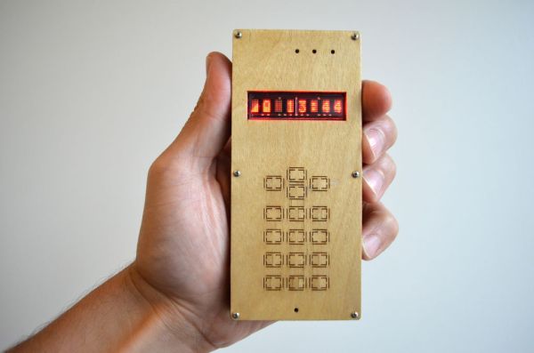
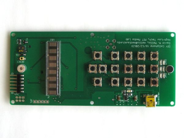
The DIY Cellphone is a working (albeit basic) cellphone that you can make yourself. It can make and receive phone calls and text messages, store names and phone numbers, display the time, and serve as an alarm clock. It connects to GSM networks (like AT&T and T-Mobile in the U.S.) using a regular (full-size) SIM card. It builds on the hardware and software in the Arduino GSM Shield but extends it with a full interface, including display, buttons, speaker, microphone, etc. The phone is made up of a custom electronic printed circuit board (PCB), about 60 electronic components, and a laser-cut enclosure. Its hardware and software are open-source and available on GitHub (hardware, software).
Part of my motivation for making the phone — and helping others to do the same — is the fact that while cellphones are ubiquitous in our society, most of us have little idea what they’re made of or how they work. In fact, you can make a cellphone in much the same way you’d make anything else: find the right parts, figure out how to connect them together, and try to do it in a way that’s attractive and robust. Because of the ubiquity of cellphones, there are companies making the components they’re made of; with some digging, I was able to find versions of these parts that are possible to buy in small quantities and that are possible to assemble by hand. This wasn’t necessarily easy, but it’s a very different problem than trying to learn the physics needed to understand how a cellphone tower works.
I’ve been using various versions of this phone as my primary device for almost a year and have taught workshops in which others have made the phone for themselves. It doesn’t require any specific knowledge of electronics, but it does involve configuring software, soldering a lot of small components, and laser-cutting, all of which can be difficult if you haven’t done them before. I’d only recommend this project if you already have some experience with Arduino and soldering, or can find someone to help you out. You’ll also need to get access to a laser-cutter, or find an alternative way to make the enclosure for the phone.
Step 1: Ordering the circuit board and components.
You can order the circuit board (PCB) from OSH Park. It costs about $60 and you get three copies of the board.
The components for the board come from three companies: Digi-Key, SparkFun, and Arduino. The full list is available in this PDF. The total cost is about $135 plus shipping.
To assemble the circuit, you’ll need a pretty good soldering setup: a soldering iron (e.g. the WES51) with a good tip, fine-pitch solder, desolder wick, tweezers, etc. To program the microcontroller, you’ll need an AVR in-system programmer (like theAVRISP mkII) and a 3.3V FTDI Cable (or equivalent breakout board). To charge the battery, you’ll need a mini-USB cable. If you don’t already have these and aren’t interested in setting up your own electronics lab, you might try looking for a local hacker space, maker space or fab lab. Most of them should have the tools you’ll need. (And, if not, this would be a good reason to convince them to get them!)
For the laser cut enclosure, you’ll need:
- A sheet of 1/4″ / 6 mm plywood, like this craft plywood from Midwest Productsavailable at many art supply stores. (Avoid the micro-lite aircraft plywood from Midwest Products or other plywood with dark adhesive layers as they tend to burn in the laser-cutter.)
- A sheet of wood veneer, preferably with adhesive backing.
- Six M0, 5/8″, pan-head machine screws (e.g. this 100 pack from McMaster-Carr)
- Six M0 nuts (e.g. this 50 pack from McMaster-Carr)
Or, try making a difference enclosure (e.g. with 3D-printing or by milling a mold).
You’ll also need a full-size SIM card from any GSM provider. I’ve been using T-Mobile in the United States but the phone has also been tested with AT&T and in India, China, and Europe.
The PCB and GSM module may take a couple of weeks to arrive. You might try practicing your soldering in the meantime!
 BOM-2.pdf32 KB
Step 2: Soldering the electronics.
While the cellphone uses many small, surface-mount components, it’s possible to solder it together by hand with a good soldering iron and some practice. If you haven’t done surface-mount soldering before, Adafruit Industries has some good tutorials: Adafruit Guide To Excellent Soldering, SMT Breadboard Prototyping Using Breakout PCBs.
Most of the components are straightforward to solder (apart from their small size), but there are some things to note:
- Capacitors: Be careful of the polarity on the large (1000 uF) capacitors, they may explode if you solder them backwards. Use the orange stripe to orient them correctly.
- Polarity: Other components with polarity include the super-capacitor, the LEDs (note the two small green dots on one side), the ATmega1284P microcontroller (note the circle in one corner), the M10 GSM module (which has an arrow in one corner), the SIM card socket, the microphone, and the diode (note the faint grey line on one side). These components have no polarity (can be soldered either way around): the crystal (8 MHz), speaker, reset button, small capacitors, and resistors. Other components only physically align in one orientation (but make sure the transistors aren’t upside down and that the buttons aren’t rotated 90 degrees).
- Antenna: When soldering the antenna, start with the pad that faces the GSM module. That’s the one that carries the electrical signal; the others are simply there for structural support (to hold the antenna down). You may even be able to heat the solder on that pad from the top of the antenna, the heat can be conducted through the two vias (small holes) in it.
- Solder Jumpers: There are two solder jumpers on the bottom of the board, labelled “Cell” and “uC”. Solder the center pad of each to the pad labelled “uC”. (This connects the RX and TX lines from the FTDI header to the ATmega1284P on the board so that they communicate over serial. If you instead solder the center pad to the “Cell” pad, the FTDI cable connects directly to the GSM module so that you can communicate with it from the computer.)
- Speaker: The speaker is awkward to solder because it has no legs. First, apply solder to the pads on the PCB. Then rest the speaker on top of the PCB (aligning its pads with those on the board) and solder it from the bottom. You can feed in solder or melt the pre-applied solder from below. If it doesn’t work, don’t remove the speaker (you might rip its pads off). Instead, try to re-melt the solder on its pads by inserting the iron into the holes from below.
- USB Connector: Only the two outer (of the five small) legs of the USB connector are used, so you don’t have to solder the three central legs. (Do solder the four corners, though, they provide structural support).
- ISP Header: Because you only need to burn the bootloader once, I typically don’t solder pins into the ISP (2×3) header. Instead, you can insert pins into the connector on your ISP and hold them against the pins (from the top of the board) while you burn the bootloader. If you have trouble, you can solder pins to the holes but you’ll have to adjust the case to make room for it.