
Summary of Moisture Control Unit – MCU
This article guides users on interfacing a moisture sensor with a NodeMCU to display soil moisture levels on a 16x2 LCD. It details hardware assembly, wiring connections for both the sensor and LCD via I2C, and provides Arduino IDE setup instructions including library installation and code uploading. The project demonstrates reading analog data, processing it, and displaying whether the soil is wet or dry.
Parts used in the Moisture Control Unit - MCU:
- NodeMCU
- Moisture sensor
- 16x2 LCD
- Breadboard
- Jumper Wires
- Micro USB Cable
- Liquid Crystal Library
- Airport IDE
In this Instructables, you will see how to Interface Moisture sensor to your NodeMCU. And check the moisture value and the same to be displayed on the LCD.
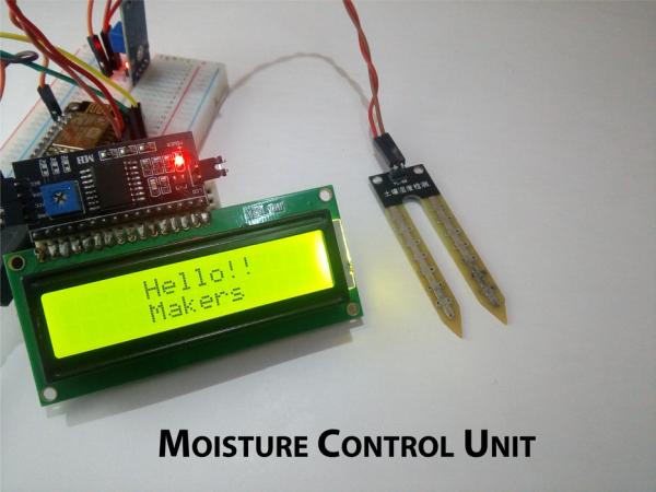
We’ll use Liquid Clear Crystal to display the moisture value. This 16×2 LCD is very popular and broadly used in electronics projects as they are good for displaying information like sensor data from your project, and also they are very cheap.
Step 1: All You Need
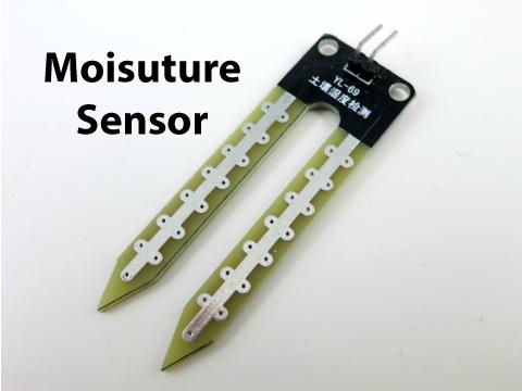
Here is the list of components required to get started with the Instructable,
Hardware Components
- NodeMCU
- Moisture sensor
- 16×2 LCD
- Breadboard
- Jumper Wires
- Micro USB Cable
Software Components
- Arduino IDE (installed with esp8266)
Step 2: Description
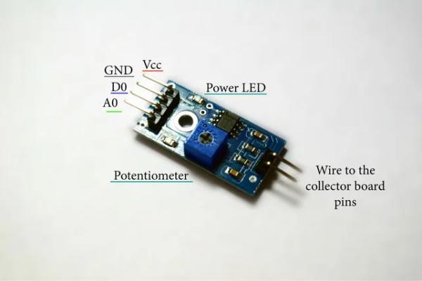
This Moisture Sensor can be used for detecting the moisture of soil or judge if there is water around the sensor, let the plant in your garden able to reach out for human’s help when they are Dry.
This sensor is very easy to use, you can just simply insert in into the soil and read the data.
Step 3: #1 Circuit Conection
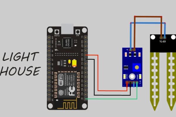
The wiring connections are made as follows:
Connect the two pins of the moisture sensor to the two pins on the Amplifier circuit using jumper wires.
Connect the Vcc from the Amplifier to the 3.3V pin on the NodeMCU.
Connect the GND pin to the ground (GND) pin on the NodeMCU.
Connect the Analog pin to the A0 pin on the NodeMCU.
Connect NodeMCU to PC via a USB cable.
After your completed with wiring connections, then insert the sensor into the soil or place it in anywhere you want
**In this Instructable I have used water for the Demonstration
Step 4: #2 Circuit Connection
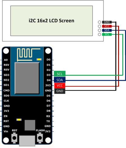
Connecting LCD to I2C and then interfacing it to NodeMCU is very simple.
The LCD’s registers from D0 to D7 and Vcc, GND, RS, R/W pins will be connected to I2C.
GND pin of I2C is connected Ground pin (GND) of the NodeMCU.
VCC pin of I2C is connected Vin pin of the NodeMCU. (Because we need to supply 5v to LCD)
SDA pin of I2C is connected D4 of the NodeMCU.
SCL pin of I2C is connected D3 pin of the NodeMCU.
Before you get started with coding you need Arduino IDE.To download Arduino IDE and for NodeMCU setup, you can check my previous Instructable.
“Interfacing Servo Motor with NodeMCU“
Step 5: Overall Circuit
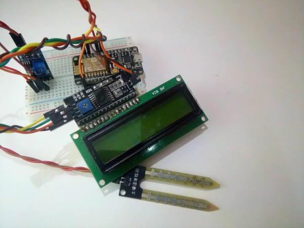
You need one paper cup with water to check if the circuit works.
Step 6: CODE
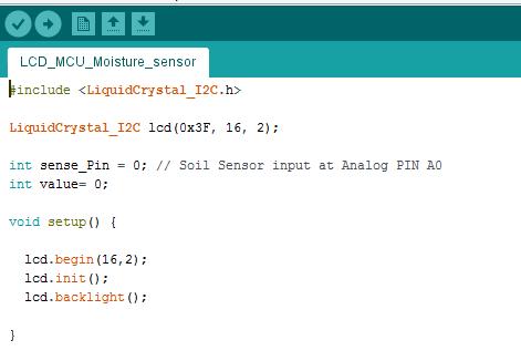
The first thing we need to do is to insert the Liquid Crystal Library.
To include Library file :
Sketch > Include Library > Manage Libraries > LiquidCrystal_I2C LCD
Download the “LCD_MCU_Moisture.ino” file and open it up in the Arduino IDE.
Then Create a new sketch and paste the code below in the Arduino IDE and hit Upload You can tinker with the code to make it more useful or just use it as it is.
#include <LiquidCrystal_I2C.h>
LiquidCrystal_I2C lcd(0x3F, 16, 2);
int sense_Pin = 0; // Soil Sensor input at Analog PIN A0int value= 0;
void setup() {  lcd.begin(16,2);
  lcd.init();
  lcd.backlight();}
void loop() {
   lcd.setCursor(0, 0);
   lcd.print("MOISTURE : ");
   value= analogRead(sense_Pin);
   value= value/10;
   lcd.print(value);
   lcd.print("%");
   if(value < 50)
   {
    lcd.setCursor(0, 1);
    lcd.print("The soil is WET");
   }
   else
   {
    lcd.setCursor(0, 1);
    lcd.print("The soil is dry");
   }
   delay(1000);
}
Step 7: Preparing the Arduino IDE
After downloading the Arduino IDE navigate to
- File tab and then click on Preferences.
- In the additional Boards, Manager URLs add the following link (http://arduino.esp8266.com/stable/package_esp8266com_index.json)
- Click OK and then navigate to
- Tools – Boards – Boards Manager
In the search field type esp8266 > click the esp8266 by ESP8266 Community – Click Install Now you have setup the Arduino IDE to work along with the NodeMCU.
Step 8: Save * Compile * Upload
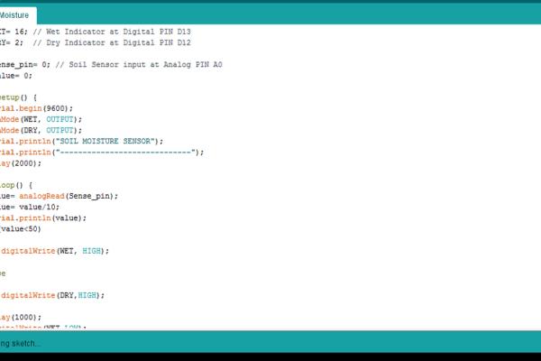
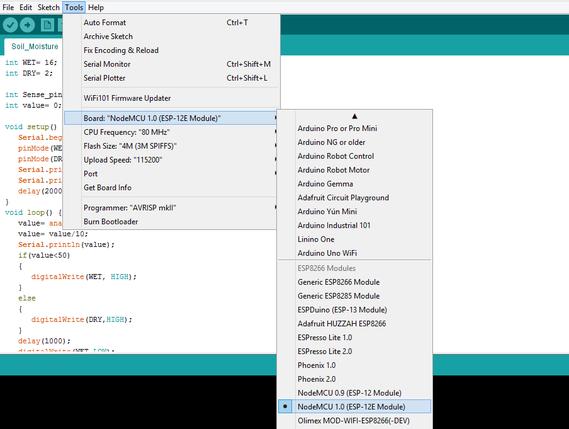
- Goto Tools
- Board > NodeMCU 1.0 (ESP – 12E Module)
- Port ( Choose the right Port )
**Make sure you have your NodeMCU model selected and the correct serial port ticked (see pics). Then just click the Upload button**
Step 9: OUTPUT
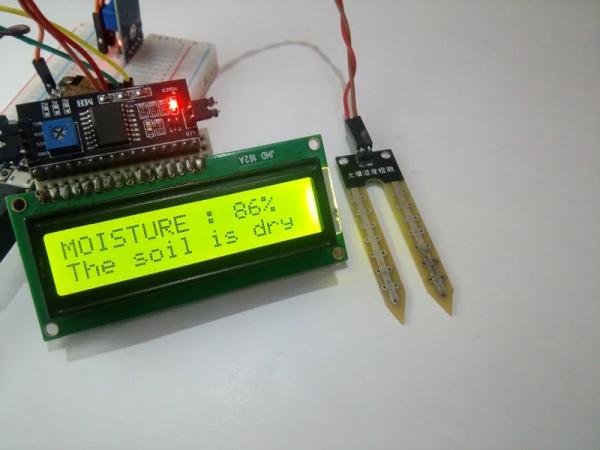
That’s all makers!
I hope you found this instructable most useful. You can contact me by leaving a comment. If you like this instructable probably you might like my next ones.
Source: Moisture Control Unit – MCU
- How do you connect the moisture sensor to the NodeMCU?
Connect the Vcc to 3.3V, GND to ground, and the Analog pin to A0 on the NodeMCU. - What voltage is required to power the LCD module?
The LCD requires 5 volts supplied from the Vin pin of the NodeMCU. - Which pins are used for the I2C connection on the NodeMCU?
The SDA pin connects to D4 and the SCL pin connects to D3. - Can this sensor detect if there is water around it?
Yes, the sensor can be used to judge if there is water around the sensor. - How do you install the ESP8266 board support in Arduino IDE?
Add the URL http://arduino.esp8266.com/stable/package_esp8266com_index.json to Boards Manager URLs and install esp8266 by ESP8266 Community. - What condition triggers the message "The soil is WET" on the display?
The display shows "The soil is WET" when the calculated value is less than 50. - Which specific NodeMCU model should be selected during upload?
You must select NodeMCU 1.0 (ESP - 12E Module) from the Tools menu. - Where should the sensor be placed to function correctly?
The sensor should be inserted into the soil or placed anywhere you want for demonstration.
