Summary of Gyroscope Platform/ Camera Gimbal
This article details a university project creating a 3D-printed gyroscope platform using an Arduino Uno R3 and MPU6050 sensor. The build involves designing custom arms in Autodesk Inventor, printing them with PLA filament, and assembling three MG996R servos to control Yaw, Pitch, and Roll movements. The system is powered by two 9V batteries and controlled via custom C/C++ code written in the Arduino IDE.
Parts used in the Gyroscope Platform:
- Arduino Uno R3 microcontroller
- USB cable
- MPU 6050 Module
- Metal gear servo (MG996R)
- DC Power Plug to 2-Pin Screw Terminal Adapter
- Battery Holder with ON/Off Switch for Arduino
- Jumper Wires
- PLA Filament
- Bolts and nuts
This instructable was created in fulfillment of the project requirement of the Makecourse at the University of South Florida (www.makecourse.com)
tep 1: Materials List
In order to begin the project, you first have to know what you’ll be working with! Here are the materials you should have before you begin:
- 1x Arduino Uno R3 microcontroller and USB cable (Amazon Link)
- 1x MPU 6050 Module (Amazon Link)
- 3x MG996R Metal gear servo (Amazon Link)
- 1x DC Power Plug to 2-Pin Screw Terminal Adapter (CableWholesale Link)
- 2x Battery Holder with ON/Off Switch for Arduino (Amazon Link)
- 3x Jumper Wires, Male to Female Male to Male Female to Female (Amazon Link)
- Access to 3D printer (Creality)
- PLA Filament (Amazon Link)
These are the main components of the project feel free to add more as you build your own version!
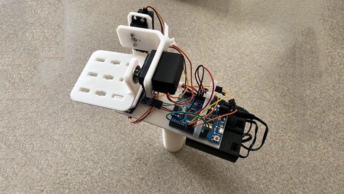
Step 2: 3D Printed Parts
The first part of this project is creating a design to hold the components together. This would include the Yaw, Pitch and Roll arms as well as a mount for the Arduino and MPU6050.
The components are designed in Autodesk Inventor as it is free for university students and then put together into an assembly. All of the part files and the assembly have been put into a .rar file which can be located at the end of this step.
Everything in this project was 3D printed with the exception of the electrical components, as such dimensions were important. In the design i gave about a 1-2 mm tolerance in order to get all parts to fit together smoothly without comprising structure. Every thing was then secured in place with bolts and nuts.
When looking at the assembly you will notice a large blank space on the platform as this is for the Arduino to sit on and for the MPU6050 to sit on.
Each part will take between 2-5 hours to print. Keep this in mind when designing because you may want to redesign to cut down on print time.
Step 3: Circuit
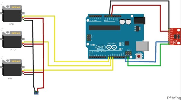
Here we discuss the electrical circuit that controls the motors. I have a schematic from Fritzing, which is a helpful software you can download here. It is a very useful software for creating electrical schematics.
The board and the servos are both powered by a 9v battery each held in its respective battery holder. The power and ground wires of the 3 servos will need to be joined and then connect with their respective pin on the 2 pin screw terminal in order to power the servos. While the MPU6050 is powered via the Arduino 5v pin. The signal pin of the Yaw servo goes to pin 10, the Pitch pin goes to pin 9 and the signal pin of the Roll servo goes to pin 8 on the Arduino.
Step 4: Code
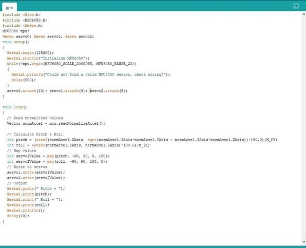
Here is the fun part! I have attached a .rar file containing the 2 version of the code for this project. which you can find at the end of this step. The code is fully commented for you to look through as well!
-The code is written for Arduino and is written in the Arduino IDE. The IDE can be obtained here. The IDE uses the C/C++ programming languages. Code written and saved in the IDE is known as a sketch, and part of the sketches you can include files from class as well as libraries you find online for your components.
Step 5: 3D Print & Assembly
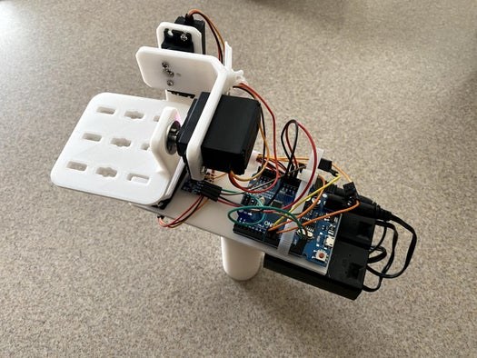
Once the 2 arms are printed along with the platform you can start assembling the gyroscope. The components are held together via the servos which are mounted on each arm and the platform by bolts and nuts. Once assembled you can mount the Arduino and the MPU6050 onto the platform and start following the circuit diagram.
-3D printers run on g-code, which is obtained by using a slicer program. This program will take the .stl file of the part you made in your CAD software and convert it into code for the printer to read and print your part. Some popular slicers include Cura and Prusa Slicer and there are many more!
-3D printing takes a lot of time but this can vary depending on the settings of the slicer. To avoid long print times you can print with an infill of 10% as well as changing the print quality. The higher the infill the heavier the part will be but it will be more solid, and the lower the quality the more you will notice lines and an uneven surface in your prints.
Source: Gyroscope Platform/ Camera Gimbal
- What software is used to design the 3D parts?
Autodesk Inventor was used to design the components as it is free for university students. - How much tolerance was applied during the design process?
A 1-2 mm tolerance was given to ensure parts fit together smoothly without compromising structure. - Can I use different slicer programs for 3D printing?
Yes, popular options include Cura and Prusa Slicer which convert .stl files into g-code. - How can I reduce 3D print time?
You can reduce print time by printing with an infill of 10% or changing the print quality settings. - Which pins on the Arduino connect to the servos?
The Yaw servo connects to pin 10, the Pitch servo to pin 9, and the Roll servo to pin 8. - How are the servos powered in this circuit?
The servos are powered by a 9v battery held in a battery holder connected to a 2-pin screw terminal. - Does the MPU6050 module share power with the servos?
No, the MPU6050 is powered via the Arduino 5v pin while the servos have their own 9v supply. - What programming language is used for the code?
The code is written in the C/C++ programming languages within the Arduino IDE.