Summary of Make a Digital Photo Album by ESP32
This article details building a digital photo album using an ESP32 3.2" TFT Touch with Camera module to display JPG images from an SD card. The project features automatic and manual image switching via touch or a timer, supports GIF playback by converting them to sequential JPGs, and requires pre-scaled images to fit the 320x240 screen resolution.
Parts used in the Digital Photo Album:
- ESP32 3.2" TFT Touch with Camera
- SD card
- JPG format pictures
- GIF images (converted to JPG)
Last week I made an electronic photo album that I could place on my work desk to show some photos. I can take a look at relaxing when I’m tired at work. Previously I have implemented the display of pictures in which the format is BMP on LCD. Nowadays most of the pictures we get using mobile phones, or cameras are in JPG format that not work on LCD.
In this tutorial, I want to share how to build a digital album that can display pictures in JPG format. This tutorial was going to achieve the goals:
- Read and display JPG format pictures from the SD card.
- Switch pictures automatically or manually.
Supplies
ESP32 3.2″ TFT Touch with Camera
Step 1: Hardware
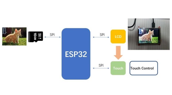
The ESP32 TFT LCD with Camera module is equipped with a 320 x 240 LCD display, which uses the ili9341 drive library. The touch chip STMPE610 is equipped on the board for touch control. In addition, the SD card module has been integrated on the board.
The ESP32 TFT LCD with Camera meets all my needs that I don’t have to look for other modules. If you have all of those modules to replace it, you can build your own digital album.
Step 2: Arduino IDE Setup
1. Install the ESP32 Board.
2. Install the TFT_eSPI library. Don’t forget to update the UserSetup.h file in the library base on your hardware. I will list the code where you need to update in the following.
// Only define one driver, the other ones must be commented out
#define ILI9341_DRIVER
//#define ST7735_DRIVER      // Define additional parameters below for this display
//#define ILI9163_DRIVER     // Define additional parameters below for this display
#define TFT_MISO 12//19
#define TFT_MOSI 13//23
#define TFT_SCLK 14//18
#define TFT_CS   15  // Chip select control pin
#define TFT_DC   33// 2  // Data Command control pin
//#define TFT_RST  // 4  // Reset pin (could connect to RST pin)
#define TFT_RST  -1  // Set TFT_RST to -1 if display RESET is connected to ESP32 board RST
3. Install the TJpg_Decode library to decode the JPG.
4. Install the Adafruit STMPE610 library.
Step 3: Firmware
1. Github: https://github.com/Makerfabs/Project_Touch-Camera-ILI9341/tree/master/example/Album_V2
2. Get a list of JPG pictures on the SD card.
int get_pic_list(fs::FS &fs, const char *dirname, uint8_t levels, String wavlist[30])
file_num = get_pic_list(SD, "/", 0, file_list);
3. Because the SPI pins (SPI_SCLK/SPI_MISO/SPI_MOSI) are shared, the selection signal needs to be set manually when using SPI communication to ensure the success of the communication. It means ESP32 communicate with the SD module by SPI when the chip selection signal of SD module is LOW and the other chip selection signal is HIGH.
#define SPI_ON_TFT digitalWrite(TFT_CS, LOW)
#define SPI_OFF_TFT digitalWrite(TFT_CS, HIGH)
#define SPI_ON_SD digitalWrite(SD_CS, LOW)
#define SPI_OFF_SD digitalWrite(SD_CS, HIGH)
#define STMPE_ON digitalWrite(STMPE_CS, LOW)
#define STMPE_OFF digitalWrite(STMPE_CS, HIGH)
4. The TJpg_Decoder.h library provides a function that reads JPG picture data directly from the SD card and displays it on the screen.
TJpgDec.drawSdJpg(0, 0, file_list[file_index].c_str());
5. Gets the position value of the screen when touched.
if (touch.touched())
    {
        // read x & y & z;
        int pos[2] = {0, 0};
        delay(100);      // delay for SPI receive the data
        while (!touch.bufferEmpty())
        {
            touch.readData(&x, &y, &z);
            pos[0] = x * 240 / 4096;
            pos[1] = y * 320 / 4096;
        }
Step 4: Prepare the Picture
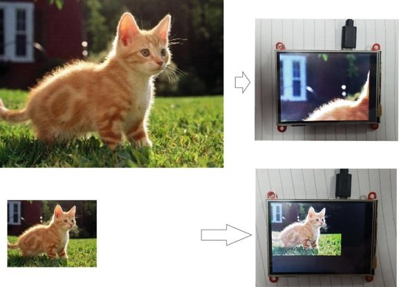
We usually use mobile phones or cameras to take pictures. The size of the photo is much larger than the LCD. When you display these pictures directly using LCD, the entire picture is not fully displayed. We need to use image processing software in advance, such as the drawing tool on Microsoft system, to compress and trim the picture to 320 x 240 size.
Copy the prepared picture to the SD card and insert the SD card into the module. Restart the module and a digital album is completed.
Step 5: Switch the Picture
1. Touch the right half of the screen to switch to the next picture.
2. Touch the left half of the screen to switch to the last picture.
3. If no touch, the picture will be switch automatically after ten seconds.
Step 6: Playing GIF Images
In addition, I used the website to convert some GIF images into many JPG images and play them with the digital album. Just set ESP32 to switch images at a very fast speed, the LCD will play a GIF picture. Although this method can be used to play small size GIF images only.
Source: Make a Digital Photo Album by ESP32
- How do I prepare images for the LCD display?
You must use image processing software to compress and trim photos to a 320 x 240 size before copying them to the SD card. - Can this device display GIF images?
Yes, you can convert GIF images into many JPG images and set the ESP32 to switch images at a very fast speed to simulate playback. - What happens if there is no touch input?
The picture will switch automatically after ten seconds of inactivity. - How do I manually switch to the next picture?
Touch the right half of the screen to switch to the next picture. - How do I go back to the previous picture?
Touch the left half of the screen to switch to the last picture. - Which library is required to decode JPG files?
You need to install the TJpg_Decode library to decode the JPG format. - What is the purpose of updating the UserSetup.h file?
Updating this file configures the TFT_eSPI library based on your specific hardware settings. - Why are SPI pins shared between modules?
The selection signal needs to be set manually because SPI pins are shared to ensure successful communication between the ESP32 and the SD module.