I have a FlashForge Finder 3D printer that did not come with a heated bed. The factory build plate is also somewhat limiting in what kind of build surfaces you can use. I finally decided it was time to resolve those issues and added a heated bed. For my project, I needed to convert the built plate from the factory version and designed an adapter so that I could mount the heated bed I used in this project. If you have this printer, check out my adapter on Thingiverse. This Instructable focuses on the heated bed and controller, so you will need to tackle mounting the heated bed for your printer.
Please read through this Instructable before jumping in and feel free to adjust and use the parts and methods that you have handy or are comfortable with. When I started on this project I had a hard time finding any clear instructions, so I worked through each part of the build and tested until I understood how to make it work and then I pulled it all together. I encourage you to use a breadboard and test it as well before you break out the soldering iron! I hope this helps other looking to do this, or a similar project!
Supplies
Here’s what you will need:
MOSFET – This is used to control the current to the heated bed and run it with an Arduino. Note, the one linked supports a PWM signal. ($15)
Arduino – I used a Nano clone. The project doesn’t require much horsepower, so any Arduino will do. (<$5)
Buck Converter – This lets us step down the 12v from the power supply to 5v to power the Arduino. ($1.50)
USB Adapter – The Arduino Mini that I used requires a mini USB for power. You can use any cable that you can sacrifice and cut off just enough to cable the power. ($4)
10k Potentiometer – I had one from a sensor kit. You should be able to use any that you have handy or can pick one up. (<$1)
Display – I’m using an OLED display because I like the clean interface. You could easily adapter this for any display you prefer. ($9)
12v Power Supply – Any 12v supply with about 30 amps will work. ($30) In theory, if your printer has a 12v supply and can spare the amps for the heated bed you could leverage that. Mine did not, so I used this external one.
Heated Bed – You can’t beat the price for this one. It proved to be well made and worked great. ($10)
Power Switch – This used a common computer power cord, includes a fuse, and give the project a finished look. ($8)
Print Surface – Once you add the heated bed you will need to put a print surface on it. I used a magnetic PEI flex plate because they make it super easy to remove prints. ($27) You can use anything you like, including the typical piece of glass from your local hardware store.
Misc – I used wire that I had on hand, including breadboard jumpers for the low voltage and heavier wire for the 12v cabling. Heatshrink tubing is great for protecting the connections. If you use the 3D printed case I include, then you will need M3x8 screws for the lid and screws for attaching your power supply. 1/2″ expandable sleeve for the wires going to the heated bed. For the power connections I used crimp connectors that I picked up from my local hardware store, including female blades for the power switch and spade connectors for the power supply.
Tools – A soldering iron and solder, and hex wrenches or a screw driver for putting the case together. A 3D printer and filament that can handle the case if you wish to use it (200 x 200 print area). I used a glue gun to mount the display in the case.
Step 1: The Hardware
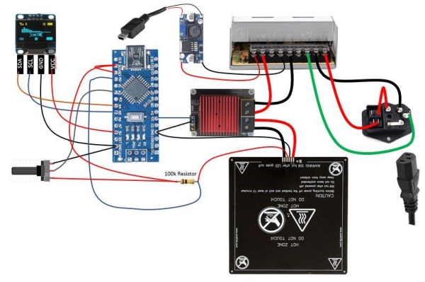
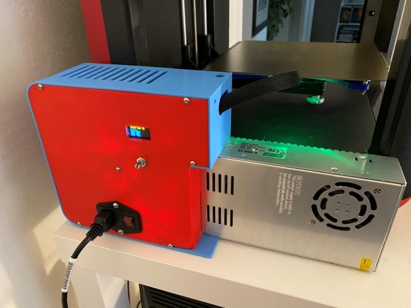
Rather than walk step by step through assembling the hardware, I thought it would be easier to see the final product. You can use this as a guide and adjust as needed if you use different hardware. Here are some notes about this build and why it was done this way.
The Heated Bed – The bed came with a thermistor built in and a cabling harness. That made it easy to incorporate in the project. The thermistor was a 100k version, so the resistor needs to match. Adjust as needed for yours.
Power Supply – The power supply has a potentiometer on it to adjust the output voltage. Be sure to adjust it to get as close to a steady 12v as possible.
USB Adapter – You just need this to power the Arduino. Be sure to match the adapter to what you need for your Arduino. The version that I used needed a mini USB, but your might use a barrel connector or micro.
Arduino – Note that the 3.3v is used for reading the thermistor (temp) and it also is fed to the reference pin. The 3.3v is better filtered than the 5v and by feeding it the ref we get a more stable reading. It might be hard to see in the diagram, so I wanted to point it out.
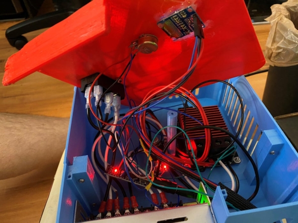
Optional – Control Box
If you use the control box I include, you may need to drill the holes to make assembly easier. Depending on the potentiometer and display you use, you may need to adjust the cover. You can do that in Tinkercad, which is a free online tool. I printed my box on the FlashForge with the new build plate, so I had to split it to fit. I printed the cover on my Ender 3, so it could be done as a single part. There is more space than needed, and it doesn’t really provide mounting for the Arduino or Buck Converter, but with the extra space it wasn’t an issue for me.
Step 2: The Code
I tried to keep the code as simple as possible. It pulls together several examples/tutorials and then I added in my own logic for controlling and setting the temp. Because I don’t expect to print more than PLA and PETG on the printer, I limit my temp range to 50 – 100. If you need to get to 110 or higher on the bed, you will need to adjust the logic.
The code is attached as an INO file so it can be opened in the Arduino IDE. It is well commented, so please review it for functionality.
Step 3: The Case
Depending on the components you use, the case I designed may not work for you. However, if you use the same parts as I did, and have a 3 printer that can handle the prints, feel free to use my design or adjust it as you see fit! Note that I use M3 screws for all the cover mounting and the MOSFET. The power supply used M4 screws. I broke off the nib on the potentiometer to mount it flat, and a glue gun to mount the display. Finally, I used a 1/2″ expandable sleeve on the wires that connect to the heated bed to tidy them up and protect them.
Source: 3D Printer Add-on Heated Bed