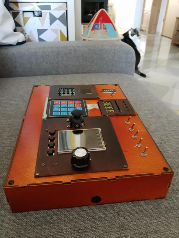
Since getting an Arduino starter kit I was wondering what to make of all those fancy buttons, shiny LEDs, touchscreen LCD displays… I was thinking about weather station, but I was told that in the maker’s world, weather station is like a “Hello World” app. Like playing “Stairway to Heaven” in a guitar store. Then, when chasing away my kid from oven’s controls for 20th time, it struck me – I could make her a spaceship-like control panel (and I still made a weather station anyway, in a separate project…).
There are plenty of examples of such projects in the Internet, but still, here’s my medium quality stab at it. I didn’t want to stick to just backlit pushbuttons and lever switches. On the other hand, there’s not much point in making a fully-fledged control panel which interacts with Kerbal Space Program for a two year old, does it? Idea was to have something relatively simple at first, but with complexity hidden in software. This way, assuming the target audience is even remotely interested, project could grow in complexity over time.
In the meantime, it would be a nice way to learn things, especially when it comes to mechanics and assembly of things. And boy, did I learn.
Supplies
Here’s the supply list for the final version of the build.
- two Arduino Uno boards (although any other would do just fine)
- 2.8″ LCD TFT Arduino shield
- KY-040 Rotary Encoder module (with knob)
- Arduino joystick module
- two MCP23017 I2C GPIO expander modules
- an 8-bit PCF8591 8-bit I2C analog-digital converter module
- LGB LED Arduino module
- Robotdyne 4 digit 7 segment display module
- an 8×8 LED matrix module (as a result of a purchasing mistake, I’m using a Wemos D1 LED matrix shield. Robotdyne’s 8×8 LED matrix is better choice)
- 4×4 keypad module
- 4 tactile push buttons
- 4×4 membrane alphanumeric keypad
- battery level indicator
- 4 lever switches (Single Pole Single Throw or Single Pole Double Throw)
- 2 impulse (on-on) switches
- 1 battery level indicator
- ~30 M2x10 screws
- 4 M3x5 screws
- M3x50 distance bolts
- ~40 female-female DuPont jumper wires
- ~40 female-male DuPont jumper wires
- one of: a couple of prototyping PCBs or a breadboard or a prototyping Arduino shield
- when using prototyping PCBs or Arduino shield – also some wires and connectors
- two 18650 li-ion battery cells with basket
- two 2.1/5 DC barrel jack plugs
- a 2.1/5 DC barrel jack connector for encasing
- 2S BMS circuit for charging the battery cells
- 11 3mm LEDs, different colors
- 4 220R resistors, THT
You can get most of these supplies in one of the Arduino Starter Kits for a reasonable price. Make sure that you’re using LED modules with driver circuits rather than plain LEDs.
Step 1: The Concept
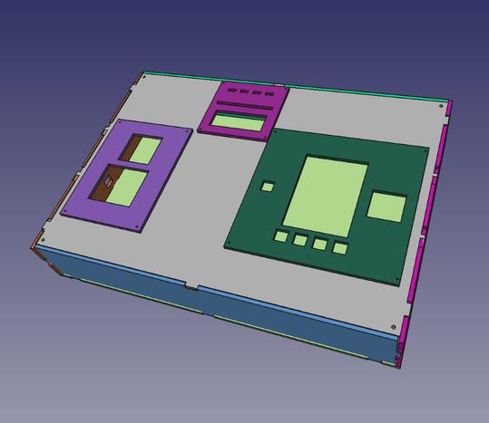
Creating a concept of how the panel would look like is a first step. A rough idea of how big the panel would have to be to accomodate all components is a prerequisite to laying out connections to Arduino. So, I made a design of the case in FreeCAD.
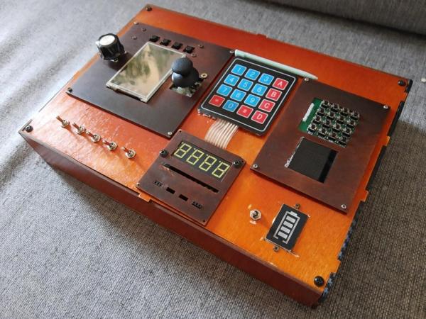
Initial idea was to model the control panel after planes’ avionics (inspiration drawn mostly from F-18’s cockpit): have three instrument panels connected to the main case using M2 screws. Each panel would have cutouts for components: LED matrix and keypad to the left, 7-segment display and some LEDs in the top-center, and LCD shield with rotary knob, joystick, and some buttons to the right. There were no lever switches or alphanumeric keypad in the original design, those were added later on, as initial assumptions were proven to be incorrect.
Incorrect assumption #1: I2C GPIO Expander Can Drive LEDs. I guess this is what you get for buying components without spending two seconds on their datasheets.
Initially, all LEDs in the design – both standalone, and segment/matrix displays – were meant to be connected via GPIO expander modules to the Arduino. As it turned out, GPIOs in these devices do not output nearly enough current to power a LED. All LEDs would have to be connected directly to the Arduino, and there are simply not enough GPIOs to drive everything. This had to be solved by an emergency purchase of LED modules with integrated driver circuits. These modules require only two pins to be connected to Arduino, and the current drivers are on board.
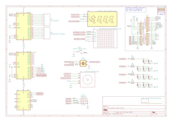
As seen in the top-right corner of the schematic, initial design had space for four backlit touch buttons. Central component panel also has cutouts for them (four small cutouts at the very top). These modules, however have proven to be not very user friendly. Also, cutouts were too close to each other to accommodate four modules, so I threw them out entirely. In the course of developing software for Arduino there were a lot more changes, so the diagram here is just an illustration of a general concept for this control panel.
Step 2: The Casing
I used FreeCAD’s Part Design and Sketcher workbenches to design the casing. First, a Body has to be created for any given piece of the casing. Here, casing is built using nine parts (Bodies, in FreeCAD’s lingo):
- front panel
- back panel
- four walls
- three component panels
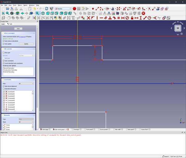
In FreeCAD part design starts with a sketch. Each panel is being drawn as viewed from top, with all edges, cutouts, and screw/mounting holes, and then extruded along an axis. This operation creates a solid body as the software takes an input sketch and “raises” it by specified distance – 3 mm in this case.
Once all panels are created, they can be moved around using FreeCADs “Transform” operation, which allows for moving the part along each axis and rotating it as needed. All done in 3D, so this is great for seeing how the parts would fit together.
Somewhere between drawing a rough concept and buying wood to cut the casing I realized that it would make more sense to have all the panels cut out on a laser cutter. This way I could save some time in the build and achieve quality well beyond my reach, given my set of skills and tolls for woodworking.
So I added small notches on each panel, 10mm x 3mm, so that each panel can be snapped together and held mostly by friction. I also received great advice from the company which did the laser cutout: laser cutter’s precision is ±0.5 mm, so if the notches are supposed to hold the casing together, notches have to be slightly bigger. For that reason actual notch is 10.4mm x 3mm, as seen on the drawing. Adding extra 0.2 mm on either side helps to mitigate a worst case scenario, in which laser cutter would be 0.5 mm off and make the cutout at 9.5 instead of 10mm. Also extra 0.2mm on each side makes for a tighter fit.
Since this is a kid’s toy it shouldn’t rely only on glue and friction to be held together. For that reason four screw holes are added in corners of front and back panel. Idea is to use 50mm distance screws to squeeze entire device together.
One of the side panels has a square cutout for DC barrel socket. Turned out that I only could get round barrel sockets, so it would’ve been better if the cutout was round. Still few seconds with a 10mm drill did the trick.
Back panel has four mounting holes in Arduino’s Uno layout, for easy assembly.
Some remarks in hindsight, stuff I would’ve done differently now:
- front panel should also have cutouts for battery level indicator and lever switches. I added those components late, so had to do the cutting manually. While lever switches are easy – just a 5mm hole, I did some damage to the panel when cutting out hole for the battery level indicator
- second set of Arduino mounting holes would be nice. I thought that a second Arduino – connected to the LCD TFT shield – would just hang underneath the panel, plugged in with the LCD shield. Sadly, it didn’t fit.
- cutouts for USB ports (or at least place to expose Arduino’s serial ports as pins) would be super useful.
- placement of component panels could be improved. Actually, I should’ve grabbed 3D models of all the components to see how they fit together. That would’ve saved me some trouble during assembly.
- notches on the walls are not symmetrical. Painting and assembly would be bit easier if they were.
I used nitrocellulose hard paint for the panels, mostly because I had a couple of cans lying around. Any type of coating would do (actually, I had to cover one of the panels with carbon foil, because it turned out I painted it on the wrong side…).
Step 3: The Assembly
Now that the casing, and constraints it poses on the entire device, are more or less finalized, it’s time to connect all the wires.
Since this project relies heavily on I2C interface, it makes sense to start with it. On Arduino Uno I2C pins are routed to both separate pins and to A4/A5 outputs. I suggest using the separate pins – P3.1 and P3.2 on the schematic. All the I2C devices have to be powered as well, so total of four lines (SCL, SDA , +5V, and GND) should be connected to the I2C breakout board (or the breadboard). These lines should go to both GPIO expander modules (let’s call them GPIO_A and GPIO_B for easier reference) and an ADC module.
Both GPIO expander modules need to have their reset and addressing pins connected. Reset is an active low pin, so it has to be connected to +5V (ideally through a resistor). Address pins have to be set up so that both devices can operate on the I2C under different addresses – i.e. can be distinguished from one another. I’ve set up address pins on GPIO_A to zero (all connected to ground), and on GPIO_B to one (A0 connected to +5V, rest to ground). These settings translate to I2C addresses 0x20 and 0x21, respectively. Default address for ADC module is 0x48, so no conflicts here.
Rotary encoder pins A and B have to be connected to Arduino Uno pins 2 and 3. These are the only two pins with interrupt capability, and using interrupts rather that repeatedly ask for value update creates a much smoother user experience.
RGB LED module needs to be connected to PWM-capable pins (marked with a ‘~’ sign on the Arduino board). PWM capability allows for brightness adjustments.
7-segment display power, LED matrix power, and the second Arduino (Arduino B, as called on the schematic; ones that drives TFT LCD screen) are connected through switches.
There are also two momentary lever switches (the ON-ON ones). One is used to enable battery level display LED, the other is wired to the ground to serve as a reset for Arduino A.
The custom four-color LED bar is using 3mm color LEDs, all connected to separate pins on Arduino using 220R series resistors to limit the current draw. A higher value can be used to dim the LEDs a bit.
Since the CAD drawing was more of a rough idea than a detailed design, I had to resort to using huge amounts of hot glue. It looks rather nasty but it keeps things in place; and since its on the inside of the casing, then who cares, right…?
Most of the components are glued and/or screwed to the front panel (or the top, depends on how to look at it). Both Arduinos and stuff related to power delivery (battery cells, battery protection circuit board, power breakout board) are mounted inside the casing. RGB LED module is also mounted (glued, in my case) inside, right beneath the 4×4 keypad module. There’s roughly a 2cm distance between the keypad’s PCB and the LED itself, so the RGB LED lights up entire board, which creates a rather cool effect.
Second Arduino Uno – Arduino B – is connected only to the LCD TFT shield. I couldn’t fit it when connected directly to the display shield, so I had to use wires instead. Note that all eight data lines, all SPI interface pins, and +5V and +3.3V have to be connected.
Step 4: The Code
So, what should this device even do… Given set of components used, I was thinking it could:
- display characters from the alphanumeric keypad on the 7-segment display
- turn on LEDs in the 8×8 matrix when keys are pressed on the 4×4 keypad (no particular pattern, can be random)
- display some patterns using the 4-color LED bar
- use the four tactile buttons to switch modes of operation for joystick and encoder:
- control the LED bar
- control the RGB LED’s color
- control LEDs on the 8×8 matrix
That’s for Arduino A. Since Arduino B is connected only to the LCD TFT display, it would run some sort of a sketchbook/paint application.
- There are very few custom hardware components here, so most of the software would be handled by Arduino libraries. Libraries used:
- Encoder – for rotary encoder
- Adafruit MCP23017 – for GPIO expanders
- TM1637 for 7-segment and LED matrix modules
- Keypad – for all kinds of keypads (library is versatile enough to even correctly handle four tactile buttons used here)
- Adafruit PCF8591 – for ADC module
- MCUFRIEND_kbv – for controlling LCD TFT display, including touch
One caveat here is that TM1637 library assumes it is working with a common cathode/anode 7-segment digit display, so when applied to a LED matrix, all diodes across matrix’s diagonal are lit. This should be easily fixable via software update and use of a proper library for a LED matrix.
I did add some custom wrappers for some of these libraries so let’s go through the wrappers, first.
RGB LED wrapper
This wrapper is used to provide high level interface for controlling the RGB LED, including conversion of cartesian, XY coordinates, to red-green-blue values. Library uses structure and helper methods for rgb color definition from ESPHome project.
class RgbLed
    {
    private:
        /* data */
        uint8_t pin_red;
        uint8_t pin_green;
        uint8_t pin_blue;
    protected:
        Color color;
        void setRGB(void);
        uint32_t hsv2rgb(uint16_t hue, float saturation, float value);
    public:
        RgbLed(uint8_t pin_red, uint8_t pin_green, uint8_t pin_blue);
        ~RgbLed();
        void setColor(rgbled::Color color);
        void lighten(uint8_t amount);
        void darken(uint8_t amount);
        void changeBrightness(int delta);
        Color getColor(void);
        uint32_t rectToRGB(float x, float y);
    };
setColor method is a primary one, used to set a specific color. Colors are defined as a structure of three float values, in range 0..1. lighten(), darken(), changeBrightness() are used to perform basic operations on the color being currently set.
Last method rectToRGB(x,y) – is a bit more complicated. It is meant to convert (x,y) coordinates – e.g. coming from the joystick – to RGB values. Idea is to be able to change RGB LED color by turning a fully tilted joystick around – from red, through green, to blue, and back.
Let’s get on with some trigonometry then. rectToRGB(x,y) method is based on an atan2(y,x) function which calculates an angle – θ – between OX axis and given coordinates. Values of angle returned by atan2 function are in range −π < θ ≤ π. Luckily, math.h library in Arduino implements this function.
Using atan2 allows for converting (x,y) coordinates to an angle, but what about radius? Radius calculation is pretty straightforward, but for sake of simplicity I’ll be just sticking to angles. Code snippet below shows application of Arduino’s atan2 function. Calculation of the angle is done only when joystick is tilted in either direction (coordinates from joystick are floats in -1..1 range; more on this later).
if (abs(x) > 0.1 or abs(y) > 0.1)<br>{
    theta = atan2(y, x) + PI;
}
float ro = sqrt(x * x + y * y);
Easiest approach to converting angle to (r,g,b) value would be to devise a set of piecewise linear functions, in which each of the color coordinates is a function of angle. This would, however, produce color changes that are too sharp. Piecewise sin() function would create a smoother transition. Sinus function is great for describing cyclical phenomena; since goal here is to convert a cyclical movement of joystick to color coordinates, it’s a perfect match.
To make the transition of colors smooth, each of the color coordinates have to overlap a little – meaning that as joystick moves around, values of one of the color coordinates have to fade to 0, while other slowly raises to 1. To achieve this, each of the color coordinates is calculated with different phase shift applied to the sin() function.
Here’s the lambda function responsible for converting angle to a color coordinate:
auto cval = [](float theta, float ro, float phase, float neg_phase) {<br>            float val = sin(0.666 * theta - phase);
            if (val < 0)
                val = sin(0.666 * theta - neg_phase);
            return val;
        };
To calculate each of the color coordinates, this lambda is called with different phase shift, and calculated coordinates are used to create the color:
float r = cval(theta, ro, -PI / 2, PI);<br>float g = cval(theta, ro, 0, 3 * PI / 2);
float b = cval(theta, ro, PI / 2, 5 * PI / 2);
Color c = Color(r, g, b);
Display wrapper
Display wrapper class maintains buffers which convert raw characters obtained from keypads to raw bit values needed by display’s libraries to actually show the character.
const uint8_t digitToSegment[16] = {<br>        //XGFEDCBA
        0b00111111, // 0
        0b00110000, // 1
        0b01011011, // 2
...
Each character (‘0’, ‘1’, ‘A’, etc.) is mapped to sequence of bits which, when passed to actual display library, will light segments needed to show the character. Internal buffer has size that matches number of digits (or rows, in case of LED matrix) in the display.
Keypad wrapper
This is a very simple subclass of parent Keypad class from respective library. It overrides pin_mode(), pin_read(), and pin_write() methods from Keypad class (and the fact that these methods are declared as virtual in Keypad class is beyond cool). This is object-oriented programming model at it’s best – original pin_mode/pin_read/pin_write methods were nothing more than wrappers around native Arduino functions.
In this project, however, all keypads are connected via GPIO expanders, which precludes from using native functions. Overloading pin_mode(), pin_read() and pin_write() methods in subclass allows for re-defining their behavior to use GPIO expanders rather than native Arduino functions, without having to modify any of the behavior in the super (parent) class.
PanelKeypad(Adafruit_MCP23017 *gpio, char *userKeymap, byte *row, byte *col, byte numRows, byte numCols)<br>        : Keypad(userKeymap, row, col, numRows, numCols)
    {
        PanelKeypad::gpio = gpio;
    }

void pin_mode(byte pinNum, byte mode);

void pin_write(byte pinNum, boolean level)
{
    if (PanelKeypad::gpio != NULL)
    {
        PanelKeypad::gpio->digitalWrite(pinNum, level);
    }
}

int pin_read(byte pinNum)
{
    if (PanelKeypad::gpio != NULL)
    {
        return PanelKeypad::gpio->digitalRead(pinNum);
    }
    else
    {
        return -1;
    }
}
LED bar wrapper
This class wraps operation on Arduino pins connected to individual LEDs in the bar into a few handy methods, allowing for:
- turning individual color on/off
- animating leds to create a kind of a Knight Rider effect
void move_bar(int direction)<br>{
    // make sure that direction is either 1 or -1
    if (direction != 0)
    {
        direction = direction / abs(direction);
        LedBar::leds[led_ptr] = !LedBar::leds[led_ptr];
        LedBar::color(led_ptr, LedBar::leds[led_ptr]);
        if (direction > 0)
        {
            ++led_ptr %= numColors;
        }
        else if (direction < 0)
        {
            if (led_ptr == 0)
                led_ptr = numColors;
            led_ptr--;
        }
    }
}
Depending on a direction (positive/negative integer passed as parameter) next set of LEDs in line get’s toggled on or off.
Joystick wrapper
This class wraps all logic operations on joystick while also hiding the fact that joystick is connected to an external analog-digital converter.
    class Joystick<br>    {
    public:
        Joystick(Adafruit_PCF8591 *adc, uint8_t pinx, uint8_t piny);
        Joystick(uint8_t pinx, uint8_t piny);
        float getX(bool update_coords = true);
        float getY(bool update_coords = true);
        bool isTilted(float threshold = TILT_THRESHOLD, bool update_coords = true);
        int getDirection(float axis_coords, bool update_coords = true);
    protected:
        Coordinates coords = {0};
        void read();
   private:
        uint8_t pinx = 0;
        uint8_t piny = 0;
        Adafruit_PCF8591 *adc = NULL;
        float read_pin(uint8_t pin);
    };
Joystick module is basically a two-axis potentiometer. X and Y pins of the joystick module output a voltage scaled from GND (0) to VCC (+5V, in this case), where 0 and +5V correspond to max tilt in either axis. Because of that, a joystick in its idle position outputs 0.5 * VCC on both X and Y pins.
Joystick::read() method performs read of voltage from both X and Y pins, and converts the result to a float in -1..1 range:
auto convert = [](int value, uint16_t size) {<br>            float x = (((float)value / size) - 0.5) * 2;
            return x;
        };
It also handles communication with external ADC module via respective library.
Once tilt values from joystick are known, additional processing can be done. Joystick::isTilted() method returns a boolean true value if joystick is tilted above defined threshold (threshold can also be passed as parameter) in either direction. Joystick::getDirection() will output an integer depending on direction of the tilt.
Arduino sketch
The Arduino sketch itself is the usual initialization of required objects, with their configuration done in the setup() function. Loop continuously reads all the inputs (keypads, joystick, encoder), updates global variable which holds encoder position, calculates its movement direction, and calls handlers for screens, LEDs, etc.
Joystick and encoder behave differently, depending on selected mode of operation (mode selected via tactile buttons next to the LCD screen):
if (current_mode == RGB_LED_MODE)<br>{
#ifdef RGB_LED_CONNECTED
  rgb_led_handler(joy_sw, delta);
#endif  led_bar.move_bar(1);
}
else if (current_mode == LED_BAR_MODE)
{
  led_bar.move_bar(delta);
}
else if (current_mode == LED_MATRIX_MODE)
{
  led_matrix_handler();
}
else if (current_mode == LCD_MODE)
{
}
In RGB_LED_MODE joystick’s output is used to rotate through colors of RGB LED. LED Bar mode uses encoder to change state of LEDs in the LED bar. LED Matrix mode uses joystick to light up individual diodes in the 8×8 matrix. LCD mode is not functional, for now, as LCD is handled by the other Arduino.
The other Arduino
I did try to use a single Arduino Uno to handle all inputs/lights and the LCD TFT shield, but that turned out to be somewhat difficult, mostly due to limited amount of available pins. LCD TFT shield requires both 5-wire SPI interface (touch) and 8 wire parallel data interface (display). All those pins would have to be shared with other input devices and create interference. While random pixels being shown when an encoder’s knob is turned might be an interesting effect, that was not one I was going for. So, LCD shield is handled by a second Arduino Uno.
The other Arduino runs a tftpaint application from MCUFRIEND_kbv library, unmodified. It’s a basic paint app which allows for drawing points using few predefined colors.
The Code
Latest code for this project can be found on github: https://github.com/lukasz-tuz/kids-control-panel.
Source: Kid’s Control Panel With Arduino(s)