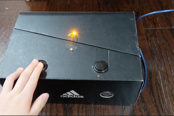
The design was inspired by a product that is also presented on Instructable called “Arduino Basics with Night Light” (https://www.instructables.com/Arduino-Basics-With-…). Originally, the device is only allowed to change the LED lights by pushing down a button; after adding the codes and circuits (added: a speaker to notify the user for using recommended relatively peaceful color-blue/a second button to turn the machine off at any time), the device is now capable of lightening the room, notifying you for turning on, and switch the machine off.
When utilizing this device, if wanting the night light to be bright yellow, simply only push the start button once, then there won’t be a combination of sounds reminding you. Under this situation, you can press the second button to turn the machine off. If wanting all functions, push the start button twice until the LED changes to blue, and you will hear a notification of turning on the night light with recommended relatively peaceful color (blue). After enjoying your dream overnight, you can push down the second button for turning off the entire machine as well.
*Actual demonstration of all functions are shown in the video in the last step, scroll down to see a detailed visual demonstration with key functions highlighted*
Before you start building your device, please note the following limitation:
*The second button cannot function while the speaker speaks
-need to wait till the speaker finishes if wanting to turn off the machine*
Step 1: Prepare Materials
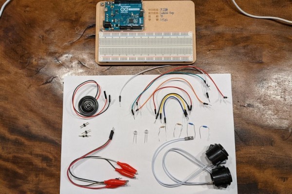
For circuits and functions:
– Arduino Leonardo board *1
– breadboard *1
– button *2
– LED lights *2 (any color you want)
– male to male wires *8
– 1K Ω resistor (blue) *2
– 100 ohm resistor (the color of three strikes in the middle-brown black brown) *2
– Arduino 0.5W speaker *1 (with female wires connected)
– alligator clip to male wires *4
– pin header *6
For connecting Arduino with laptop:
– Laptop
– microUSB to USB cable *1
– USB to typec dongle *1 (if needed)
For aesthetic need:
– shoe box *1 (need to be able to fit your Arduino Leonardo and breadboard)
– Utility knife *1
– tape *1 roll
– ruler *1 (if wanting to measure the diameters when cutting off the holes)
– decorations (optional, does not include in the steps and pictures)
Step 2: Setting Up the Board
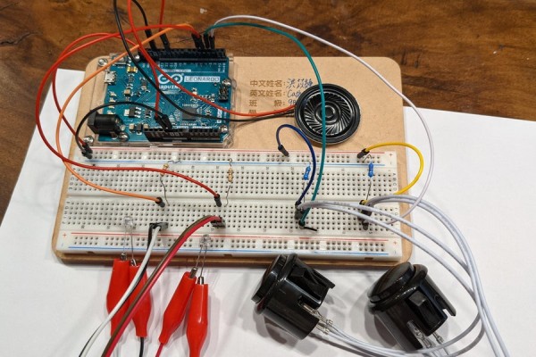
Set up your board according to the image shown above.
*female wires will need the pin header prepared aside to connect with the bread board*
Before moving on, please make sure the following points:
1. Pins from D2, D3, D4, and D5 are all aligned in the same row
2. Using the correct resistor for each (reference to the image above)
3. The positive (long leg) and negative (short leg) legs of LED lights are clipped to the alligator clip with the correct corresponding clip (long leg at the left, short leg at the right–check image #4)
4. Pins D2, D3, D4, D5, D11, and GND of the same side are correctly connected to each circuit
5. 5V is connected to the horizontal row showing a positive sign
6. GND closer to your breadboard is connected to the horizontal row showing a negative sign
Step 3: Uploading Code Into Arduino Leonardo
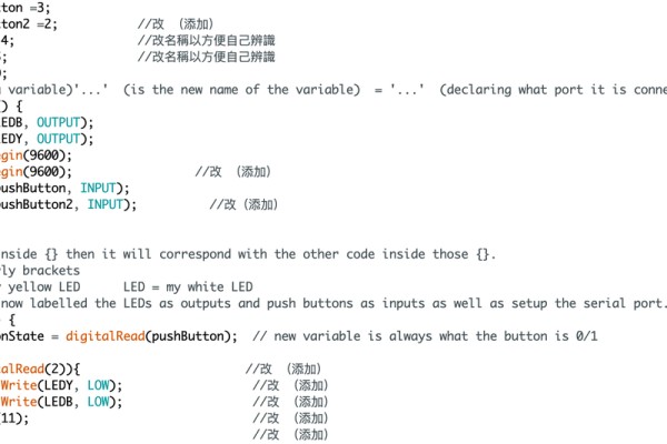
Go to this link https://create.arduino.cc/editor/catherinehung05/7… for copying the code into your computer, and further upload the code into the Arduino Leonardo board.
If this is the first time you make machines based on Arduino, please follow the steps below:
1. Download Arduino Leonardo
2. Copy the code in the link above
3. Press down the arrow symbol on the left top of the window to upload it
Step 4: Finding a Shoebox/Container to Fit the Device (Optional)
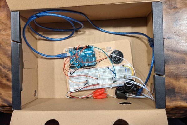
This step is optional as having a container to put this device in is not necessary. Yet I suggest you include it, it protects the device and the button will be easier for you to push down at the same time.
The shoebox I found has a dimension of 30.5 cm x 21cm x 12.5cm (length of base x width of base x height). It was quite big for this machine, but it still works. I recommend you find a box with a smaller base so that the Arduino board does not shuffle in the box when moving it. *Notice that the height of the box should be no larger than 26.5cm as the wires of buttons and LED lights are not long enough for them to reach the height (they will need to be fixed onto the top surface of the box)*
Step 5: Making Holes on the Surfaces of the Box
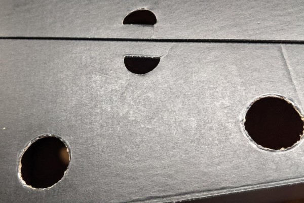
These holes are carved out for the buttons, LED lights, speaker, and microUSB to USB cable to stick out or pass through.
First, holes for the buttons. There are 2 buttons for this machine in total, therefore, we will need to carve 2 holes on the top surface of the box. When the diameter of these holes is 3.1cm, the buttons can be fixed on the top surface the best. If accidentally cut them too widely, you can stuff some thin cardboard between the gaps to fix the buttons at the position. (Note that any place on the surface is acceptable, as long as they are on the top surface of the box) (If feeling the button to be insecure, can use tape to fix them in the position)
*If you think you may confuse yourself about the functions of each button, you can use a marker to write down “on” or “off” on the box in the area above the button to differentiate them*
Second, the holes for LED lights. In my case, there is no cutting off of holes for LED lights sticking out needed. There are already 2 holes on the top surface of my box that fit the LED lights, so I don’t need to carve it. If your box does not originally have this, find two spots on the top surface of the box, and cut off 2 holes with a diameter of 0.5cm. (If feeling the LED lights to be insecure, can use tape to fix them in the position)
Third, the hole for the speaker. The best fit diameter for this hole is 3.0cm. This time, the hole should be cut in the front side of the box, which has the height of the box and the length of the box as the width and length of this surface. After cutting off the hole, remember to use the tape prepared aside to tape the speaker with the back facing out (see image #8) to the box.
Fourth, the hole for microUSB to USB cable. This hole will be at the side of the box, which has the width of the box and the height of the box to be the length and width of the surface for cutting the hole. There are no exact dimensions for this hole as there is no need to fix the cable in the position. As long as the cable can go through the hole to connect to the laptop outside the box, the hole is greatly carved.
Step 6: Putting the Device Into the Box
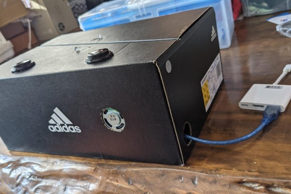
Place the Arduino and breadboard entirely into the box, and put the buttons, LED lights, speaker, and microUSB to USB cable to each corresponding hole. (According to the photos)
*Tape should be prepared aside for securing each component’s position if needed*
Source: Arduino LED Night Lights With Switch to Turn on and Off
