
Summary of Glowing Ornament
This article details the creation of a freeform glowing Christmas ornament using brass rods and 18 SMD LEDs. The project involves bending wires into rings, soldering them into an orb shape, and wiring the LEDs in segments. It offers two power options: a simple battery-powered setup with an on/off switch or a programmable version using an ATmega8L microcontroller for custom animations.
Parts used in the Glowing Ornament:
- Soldering iron
- Solder
- Soldering paste
- 0.8mm brass rod
- 18x SMD LED (yellow and red)
- CR2032 coin battery
- On/off switch
- 68Ω current limiting resistors
- ATmega8L microcontroller chip
Original glowing ornament for your Xmas tree. It’s made from brass rods wired by a freeform method and contains 18 glowing LEDs.
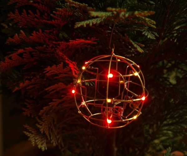
Step 1: Tools
- soldering iron
- solder
- soldering paste
- 0.8mm brass rod
- 18x SMD LED
- coin battery
- on/off switch
Step 2: The Rings
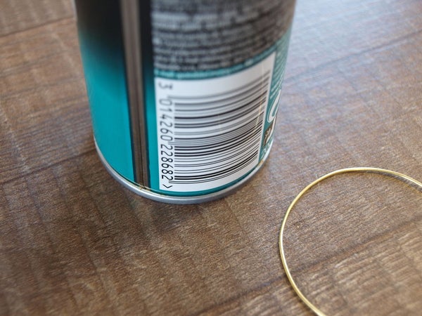
The main challenge here is to create a round shape from brass rods to look like an orb. I’ve decided to have a ball created out of 6 wires vertically and 3 wires horizontally – 18 intersections in total for LEDs to be placed in. At the bottom of the orb, there is a ring opening that will later allow me to insert an electronics to drive the LEDs.
First, start simply, found yourself a nice template for bending a wire into a circle. I am using a shaving foam can, it has a diameter of 50 mm which is exactly what I want and has a small groove near the bottom that will hold the wire while bending. After bending the wire, cut it and solder the ends together to create a nice ring. Draw yourself the same shape on a piece of paper to help you match the perfect circle. To create smaller rings I used a plastic bottle. Use whatever matches your diameter, the world is full of round stuff to bend around!
Next, I soldered the LEDs to the three 50mm rings. I’ve drawn a template on a piece of paper so every LED is in the same position. I am using yellow and red SMD LEDs. Yellow and red color because it’s less power hungry than blue or white. And SMDs to create a smooth surface of the orb.
Step 3: The Orb
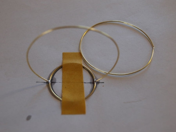
Third, I soldered rings with LEDs to the base ring which act as an opening to insert electronics. I secured the small base ring to the table with a piece of tape, trimmed the bottom of the vertical rings and soldered them to the ring creating a crown like sculpture. The first ring is soldered in one piece, the second and third is cut into halves to make a flat top of the orb.
The last step was the most frustrating and time-consuming of all. Interconnecting LEDs with curved rods to create horizontal rings. I took the rest of the rings, cut them one by one to fit into the space between vertical rings and carefully solder them.
I picked a simple pattern of placing the LEDs – two LEDs are facing each other on the neighborhood vertical rings (ground), they are connected with a piece of a curved rod which is part of the horizontal ring (power lines). So ending up with 18 LEDs grouped into 9 segments.
Tips
Always test if LEDs are still working otherwise you will need to redo the thing at the end, which is a terrible experience – I know it, it happened to me.
Great article about soldering brass – A quick guide to soldering brass.
Step 4: Make It Glow!
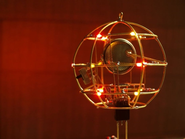
Do you have your orb? Good, now its time to make it glow. If you just want it to glow and do not care about any animation. You can stop reading right now, put a CR2032 coin battery and on/off switch inside. Connect LEDs with the battery by 68Ω current limiting resistors and make it glow! When soldering battery to brass wires, make sure not to overheat it cause it might blow.
Step 5: Programming the Ball
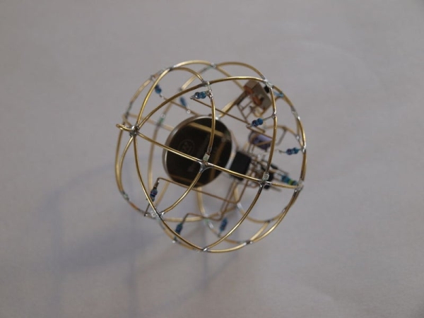
If you are like me, love Arduino and want to make it smart and have a little fun, let’s put a microcontroller into it! I pushed it even further, I wanted to make it true free-form – no PCB – no Arduino development board like Arduino NANO – and experiment with a bare microcontroller setup.
I used an ATmega8L chip – the same package Arduino NANO uses but with less memory and less power consumption. The L on the end means it has wide range of working voltage 2.7 – 5V which is great when using 3V coin battery. On the other hand, since it is a TQF32 package it was a nightmare to solder to the wires but it looks and works great.
However this will be hard to cover in just one article, so I am making a second one solely dedicated to creating a tiny programmable microcontroller to power this orb and also any other project. Stay tuned! For now here is a schematic of how I setup it for the Orbduino and few pics.
Step 6: Glowing Orb
Source: Glowing Ornament
- How do I create the round shape for the orb?
Use a template like a shaving foam can with a 50 mm diameter to bend the brass wire into circles. - Why are yellow and red LEDs chosen for this project?
These colors are selected because they consume less power than blue or white LEDs. - What is the best way to ensure the LEDs work before finishing the assembly?
Always test if the LEDs are still working early on to avoid having to redo the entire soldering process later. - Can I make the orb glow without programming?
Yes, you can simply insert a CR2032 coin battery and an on/off switch connected via 68Ω resistors. - Does the ATmega8L chip support low voltage operation?
Yes, the L version has a wide working voltage range of 2.7 to 5V, making it suitable for 3V coin batteries. - What package type does the ATmega8L chip use?
The chip uses a TQF32 package, which requires careful soldering to the wires. - How many intersections are created for placing the LEDs?
The design creates 18 intersections total using 6 vertical wires and 3 horizontal wires. - Is a PCB required for the programmable version?
No, the author aims for a true free-form setup with no PCB or standard Arduino development board.
