Building Very Low Power BLE devices made Easy with Arduino. No Android coding is required
Novice users can build BLE devices that can run continuously for over a year on a Coin Cell or 2 x AAA batteries
Update: 26th November 2019 – Added instructions for installing nRF5 Flash SoftDevice tool
Update: 24th March 2019 – Rev 4 of pfod_lp_nrf52.zip added support for GT832E_01 module and nRFChipInfo
added high drive output modes and fixed timer bug
Update: 11th February 2019 – Rev 2 of pfod_lp_nrf52.zip
Update: 6th January 2018 – Replaced BlackMagic Probe with less expensive, and less robust, Particle Debugger for programming
Introduction
This instructable, Building Very Low Power BLE devices made Easy with Arduino, is Part 1 of 3.
Part 1 – Building Very Low Power BLE devices made Easy with Arduino, this one, covers setting up Arduino to code nRF52 low power devices, the programming module and measuring the supply current. It also covers specialized low power timers and comparators and debounced inputs and using pfodApp to connect to and control the nRF52 device.
Part 2 – A Very Low Power Temperature Humidity Monitor covers using a Redbear Nano V2 module and an Si7021 temperature/humidity sensor to build a low power battery / solar monitor. It also covers modifying the Si7021 library to be low power, tuning the BLE device to reduce its current consumption of <25uA and designing a custom temperature/humidity display for your mobile.
Part 3 – A Redbear Nano V2 Replacement covers using other nRF52 based modules instead of the Nano V2. It covers selecting supply components, construction, removing the nRF52 chip programming protection, using NFC pins as normal GPIO, and defining a new nRF52 board in Arduino.
This instructable is designed to allow the novice user to build very low power BLE devices, <100uA continuously both while waiting for a connection and while connected and sending/receiving data. All that is needed is familiarity with the Arduino IDE, some soldering proficiency and a multimeter. No Android coding is required.
This is Part 1 of two parts. Very Low Power BLE, Part 2 – Temperature Humidity Monitor illustrates a practical application of this very low power programming and covers tuning for low supply current. The final Temperature Humidity Monitor uses ~25uA while connected and updating the mobile and can run for years on a coin cell.
This detailed tutorial uses Nordic Semiconductor nRF52832 chips and shows you how to code them using the Arduino IDE. It also covers how to connect to your BLE device from your Android phone and how to design custom menus and graphical displays.
Custom libraries are provided, based on Nordic’s SDK and BLE support and Sandeepmistry’s nRF5 IDE add-on and BLEPeripherial libraries. These libraries have been modified to support low power and to simplify use.
On the Android side, the tutorial uses a number of free Nordic Android apps, for testing and basic control. For custom Android displays, no Android coding is required. The free pfodDesigner Android app generates the low power Arduino code to display your own custom menus, charts, data logging etc on pfodApp. You can also build custom interactive graphical controls in Arduino code for pfodApp. No Android coding required, pfodApp handles all of that for you.
This latest version of this tutorial is also available on-line at Easy Very Low Power BLE in Arduino
Step 1: Quick Start
- Wire up the programmer, — Step 2
- Install the low power support — Steps 3 and 4
- Use the free pfodDesigner to create a custom control menu/data logger and generate the low power sketch for pfodApp to connect to and display the controls and chart and log the data. — Step 13
Boards and Programmers
Although Sandeepmistry’s original nRF5 Arduino add-on supports a number of nRF51/52 boards, this project only supports nRF52832 chips. To get the lowest power you need to use a board with just the nRF52832 chip since any extra devices like accelerometers use more power.
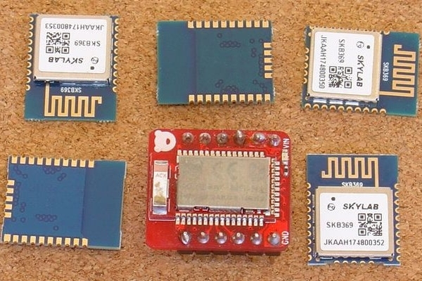
The test device is a RedBear Nano V2. This is small enough to be used for real devices. The pfod_lp_nrf52.zip also covers stripped down modules like the the SkyLab Bluetooth Module SKB369 and GT832E_01, both of which are available from https://www.aliexpress.com Although the Nano V2 board includes a low power regulator, an external regulator is used so that the bare chip boards can be programmed also. This external regulator is also needed to ensure start up from very low current sources.
To program the nRF52832 chip the Particle Debugger is used. This probe also supports low level debugging if you ever decide to delve deeper into the Nordic SKD code, but all debugging done in this project just uses Arduino Serial print statements. As an alternative the BlackMagic Probe can be used. The construction and programming using the BlackMagic Probe is described here.
Instructable Outline
Building the programming/test board — Step 2
Installing the low power support for the nRF52832 in Arduino — Step 3
How to Code for Low Power
Delays are evil. Use timers instead.
Measuring the Supply Current – Blink_millisDelay.ino
A Low Power Timer – Blink_lp_timer.ino
Extra Components Use Extra Power
Debugging Low Power
A Low Power BLE UART – lp_BLE_temp.ino
Sending data via lp_BLESerial
lp_comparator – lp_BLE_comparator.ino
lp_pinChange
High Drive Output Modes
nrf52ChipInfo
Low Power Button Debounce – lp_BLE_debounce.ino
Custom Low Power Control and Data Logging – lp_BLE_NanoV2_example.ino
Step 2: Building the Programming / Testing Board
The project uses the Particle Debugger to program and debug (via Arduino Serial prints) the nRF52832 chip. The Particle Debugger also supports GDB single step source level debugging, but that was not used in developing this low power library and you should be able to use the usual Arduino print statements to do any debugging you need for your sketch.
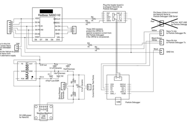
There is the schematic for the programming / testing board (pdf version).
Parts List
Approximate cost as at Dec 2018, ~US$80 including NanoV2, USB cables and USB supply (plus shipping)
- Particle Debugger ~ US$20
- USB extension Cable 1.5ft for the Particle Debugger ~US$2
- SWD (2×5 1.27mm) Cable Breakout Board ~US$2 for Particle Debugger ribbon cable
- SparkFun USB Mini-B Breakout (or Adafruit’s Mini-B version) ~US$2 (OR you can use a Micro-B break out board and matching cable instead)
- USB cable – A/MiniB – 3ft ~US$4 to suit SparkFun’ Mini-B breakout board
- USB supply ~ US$7 to power the nRF52832 chip via the breakout board and MAX8881EUT33 regulator
- MAX8881EUT33+T 3v3 Digikey MAX8881EUT33+TCT-ND ~US$2
- SparkFun SOT23 to DIP Adapter ~US$1
- Redbear NanoV2 ~ US$17
- 2 x 10uF 25V Ceramic capacitors e.g. Digikey 445-7705-1-ND ~ US$2 mounted between tracks on copper side of vero board
- 1 x 0.1uF 50V Ceramic capacitor e.g. Digikey 478-10836-1-ND ~ US$0.5 mounted between tracks on copper side of vero board
- 1 x 0.1uF Ceramic capacitor e.g. Digikey 478-2472-ND ~ US$0.5
- 1 x 330R 1/4W 1% resistor e.g. Digikey S330CACT-ND ~US$0.1
- 1 x 1K5 1/4W 1% resistor e.g. Digikey RNF14FTD1K50CT-ND ~US$0.1
- 4 x 1K 1/4W 1% resistor e.g. Digikey RNF14FTD1K00CT-ND ~US$0.4
- 470uF 25V Low ESR capacitor e.g. Digikey 399-6127-ND ~ US$1
- 2 x 6 pin and 2 x 5pin female headers sockets e.g. Sparkfun PRT-11269 ~US$2 cut down the 8pin header to use for the Particle Debugger programming breakout board
- 6 x 6 pin male header pins e.g. Sparkfun PRT-00116 ~US$1.5
- female to female jumper e.g. Adafruit ID: 1950 ~US$2
- 3mm x 12mm nylon screws, e.g. Jaycar HP0140 ~AUD$3
- 3mm x 12mm nylon tapped spacers, e.g. Jaycar HP0924 ~AUD$10
- Vero board (strip copper) e.g. Jaycar HP9540 ~AUD$5
- plastic sheet to insulate bottom of vero board e.g. cut out of plastic lid
The programmer/test board was constructed on vero board. The MAX8881 regulator provides 3.3V from the 5V USB supply. The Nano V2 has its own on board regulator, but if you want to be able to program bare modules like the SkyLab that don’t include a regulator then you will need the MAX8881, or similar. The MAX8881 has a supply current of 3.5uA (typical), similar to the Nano V2 on-board regulator. When running your low power BLE project from a very low current source, then the Power OK (POK) and Shutdown (SHDN) pins on the MAX8881 can be used to hold off the nRF52 until the 470uF supply capacitor has charged up enough current to supply the chip’s start up current surge.
In this circuit, the 470uF low ESR (Equivalent Series Resistance) is used to filter the chip’s current pulses when it transmits. This allows you to use a multimeter to get a good idea of the average supply current. The supply current is measured across two shunt resistors in the GND line. For high supply currents, short out terminals 1 to 3 to remove the resistors. For medium supply currents, short out terminals 2 to 3 to remove the 1K5 resistor. For the very low supply currents, that will be achieved in this tutorial, leave the terminals 1,2,3 open. The multimeter, or oscilloscope, is connected across the Current Monitor Test Points. If using an oscilloscope, connect the GND clip lead to the USB GND side of the shunt resistors.
The construction shown here was originally used for the BlackMagic Probe programmer so this programmer follows the same layout. The Particle Debugger ribbon cable and a header is used to program via the SWCLK and SWDIO and GND connections. A small header board is used to connect the TX, RX and GND for the Arduino Serial Debugging connection.
Unlike the BlackMagic Probe, which has a Vref connection to sense the supply voltage of the device being programmed, the Particle Debugger has a fixed 3.3V supply and no isolating buffers. This means the device being programmed should be powered by 3.3V when it is being programmed.
To protect both the device being programmed and the Particle Debugger from differing supply voltages, for example when one is powered and the other is not, 1K resistors are placed in series with the SWCLK, SWDIO, TX and RD leads. These limit the maximum current that can flow in-chip the I/O protection diodes.
In this board the NanoV2 was plugged in for ease of programming and measuring the supply current, before transferring to the final circuit. In general to program your nRF52, you need to connect the SWCLK, SWDIO, GND leads to the nRF52 and power the nRF52 with 3.3V (Vdd) while it is being programmed.
Source: Very Low Power BLE Made Easy With Arduino — Part 1