
Summary of Voice Controlled Smart Key Holder
This article details the construction of a voice-controlled smart key holder using an Arduino, Bluetooth module, and LEDs. The system allows users to identify keys via smartphone commands, with corresponding LEDs illuminating to indicate the correct lock. It is suitable for various institutions like banks and hospitals.
Parts used in the Voice Controlled Smart Key Holder:
- Arduino Uno or Nano
- USB 2.0 Cable Type A/B (for UNO) or USB 2.0 A to Mini B (for Nano)
- HC05 Bluetooth module
- Three LEDs
- Three resistors of 100 ohms
- 9V battery and its connector
- Breadboard or General Purpose Zero PCB
- Jumper wires
- Soldering iron
- Soldering wire
- Glue gun
Are you the kind of person who’s not good with managing keys and always have to try each key for every other lock?

Well don’t worry, just grab a little bit of motivation and your maker tools to innovate your very own voice controlled smart key holder. Because there’s no problem too small or big that cannot be solved and there’s no maker that cannot solve it.
All you have to do is, just ask your smartphone about the lock you want to open. Your phone will then communicate with smart key holder and corresponding LED will light up to indicate about the exact key that belongs to that particular lock.
This smart key holder can also be used in banks, hospitals, libraries, administration offices etc.
Step 1: Components Required:
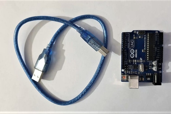
1. Arduino Uno/Nano
2. USB 2.0 Cable Type A/B(for UNO) and Cable/USB 2.0 A to USB 2.0 Mini B(for nano)
3. HC05 bluetooth module
4. LEDs(3)
5. 3 resistors of value 100 ohms
6. 9v battery and its connector
7. Breadboard/General Purpose Zero PCB Printed Circuit Board
8. Jumper wires
Apart from all these, you’l also need soldering iron, soldering wire and glue gun.
That’s pretty much everything.
Step 2: Hardware Connections
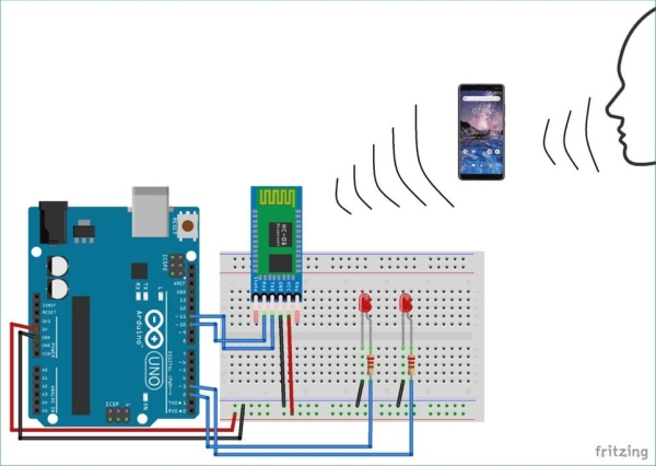
I started by creating a base/socket for Arduino Uno on zero board as shown in the first picture so that we can easily remove or attach the board according to our requirement. Then I connected HC05 bluetooth module to arduino.
- Connect Rx pin of bluetooth module to Tx pin of arduino
- Connect Tx pin of bluetooth module to Rx pin of arduino
- Connect Vcc of module to +5v of board
- Lastly connect GND of module to GND OF Uno board
Next step is to make LED connections. Longer leg of LED is positive terminal and other one is negative terminal. Solder +ve terminal of LED to any one side of resistor and connect other side to digital pin 11 of arduino. Similarly connect the positive terminals of other two LEDs to resistors and other side of resistors to pin 12 and 13 respectively. Connect the negative terminals of all LEDs to GND pin.
That’s it! We’re done with the hardware it.!
Step 3: Upload the Code
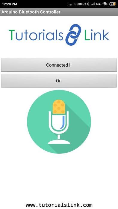
Download the app “Arduino Bluetooth Controller”
From available devices choose HC05. In order to connect your phone to bluetooth module for the first time, you need to enter either 0000 or 1234 as passkey.
Last step is to upload the given code on arduino and our work is done.
Enjoy….!
Source: Voice Controlled Smart Key Holder
-
How does the smart key holder indicate the correct key?
The corresponding LED lights up to indicate the exact key that belongs to the particular lock requested. -
What app is required to control the device?
You need to download the app called Arduino Bluetooth Controller. -
What passkey is needed to connect the phone to the HC05 module?
You must enter either 0000 or 1234 as the passkey during the first connection. -
Which pins on the Arduino are used for the Bluetooth module connections?
The Rx pin connects to the Tx pin and the Tx pin connects to the Rx pin of the Arduino. -
Where should the positive terminals of the LEDs be connected?
The positive terminals connect to digital pins 11, 12, and 13 through 100-ohm resistors. -
Can this device be used in hospitals?
Yes, the smart key holder can be used in banks, hospitals, libraries, and administration offices. -
What power source is used for the circuit?
A 9V battery with its connector powers the board. -
How are the negative terminals of the LEDs handled?
The negative terminals of all LEDs are connected to the GND pin.
