Summary of How to use a Piezo element to detect vibration using Arduino
This tutorial explains using a piezo element with an Arduino to detect vibrations (e.g., knocks). The piezo produces a voltage when deformed; analogRead converts 0–5V into 0–1023. When the reading exceeds a user-set threshold, the sketch sends Knock! over serial and toggles the LED. A 1 MΩ resistor is placed in parallel with the piezo to limit voltage/current and protect the analog input. For best sensing, attach the piezo firmly to the monitored surface.
Parts used in the Knock Sensor Project:
- Arduino board
- Piezo electric disc (piezo element)
- 1 megohm resistor
- Wires (including ground and signal lead)
- Solid surface for mounting (door, table, or other)
This tutorial shows you how to use a Piezo element to detect vibration, in this case, a knock on a door, table, or other solid surface.
A piezo is an electronic device that produces a voltage when it undergoes physical deformation from a vibration, sound wave, or mechanical strain. Likewise, applying voltage to a piezo element causes it to vibrate and generate sound. Piezoelectric devices can be utilized for both producing tones and sensing tones.
The sketch utilizes the analogRead() command to interpret the piezos output, converting the voltage range of 0 to 5 volts to a numerical range of 0 to 1023 through analog-to-digital conversion (ADC).
When the sensor’s output exceeds a specific threshold, the Arduino will transmit the message “Knock!” to the computer through the serial port.
Access the serial monitor in order to view this text.
Circuit
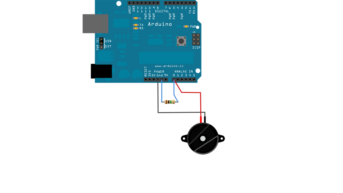
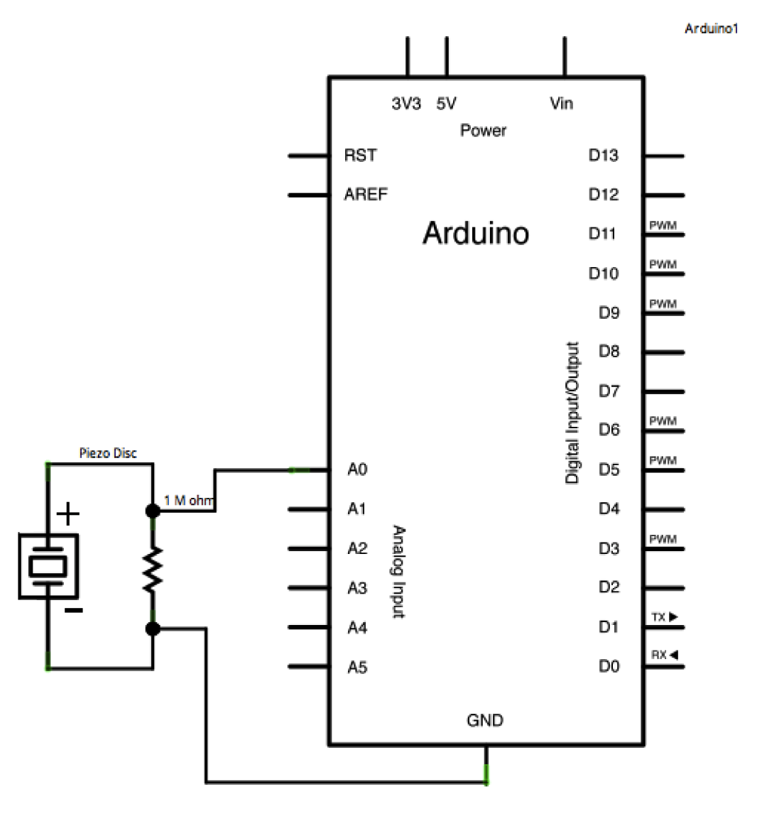
Piezos are polarized, allowing voltage to flow through them (or out of them) in a particular orientation. Attach the low voltage black wire to the ground and the high voltage red wire to analog pin 0. Furthermore, add a 1-megohm resistor in parallel with the Piezo element to constrain the voltage and current generated by the piezo and safeguard the analog input.
Piezo elements can be obtained without a plastic enclosure. These will appear as a metal disc and are simpler to operate as input sensors. PIezo sensors are most effective when they are firmly pressed against, taped to, or glued to their sensing surface.
image developed using Fritzing. For more circuit examples, see the Fritzing project page
Schematic:
Code
In the code below, the incoming piezo data is compared to a threshold value set by the user. Try raising or lowering this value to increase your sensor’s overall sensitivity.
/* Knock Sensor
This sketch reads a piezo element to detect a knocking sound.
It reads an analog pin and compares the result to a set threshold.
If the result is greater than the threshold, it writes
“knock” to the serial port, and toggles the LED on pin 13.
Hardware Required
- Arduino Board
- (1) Piezo electric disc
- (1) Megohm resistor
- solid surface
For more detail: How to use a Piezo element to detect vibration using Arduino
- What does a piezo element do in this project?
The piezo produces a voltage when it undergoes physical deformation from vibration, sound wave, or mechanical strain and is used to sense knocks. - How does the Arduino read the piezo output?
The Arduino uses analogRead to convert the piezo voltage (0–5V) into a numerical range of 0–1023 via ADC. - How does the sketch indicate a detected knock?
When the analog reading exceeds a threshold, the Arduino writes Knock! to the serial port and toggles the LED on pin 13. - Why is a 1 megohm resistor used?
The 1 megohm resistor is placed in parallel with the piezo to constrain the voltage and current generated and protect the analog input. - How should the piezo be mounted for best results?
Piezo sensors are most effective when firmly pressed against, taped to, or glued to their sensing surface. - What wires connect to which pins on the Arduino?
Attach the piezo low voltage black wire to ground and the high voltage red wire to analog pin 0. - Can the sensitivity be adjusted?
Yes; the incoming piezo data is compared to a user-set threshold in the code—raise or lower it to change sensitivity. - How do I view the Knock! messages from the Arduino?
Open the serial monitor to view the Knock! text transmitted by the Arduino.