Summary of Beat the Heat: DIY Temperature-Controlled Fan Speed Regulator
This project is a closed-loop, Arduino-based fan speed regulator that uses an LM35 temperature sensor and PWM-driven motor driver to automatically adjust a 12V fan based on real-time temperature readings, displaying temperature and fan speed on an LCD. It aims to improve energy efficiency and can be adapted to control other thermal devices. The Arduino (ATMega8/168/328) performs ADC, control logic, and drives the motor driver; the system is powered by a 12V battery and organized via PCB connectors for portability.
Parts used in the Temperature-based Fan Speed Controller and Monitoring using Arduino:
- Arduino board (ATMega8/168/328 based, e.g., Arduino UNO)
- LM35 temperature sensor
- LCD screen
- Motor driver module
- 12V DC fan motor
- 12V battery (power supply for fan)
- Connectors CON2 and CON3 (for interfacing Board1/Arduino to circuit)
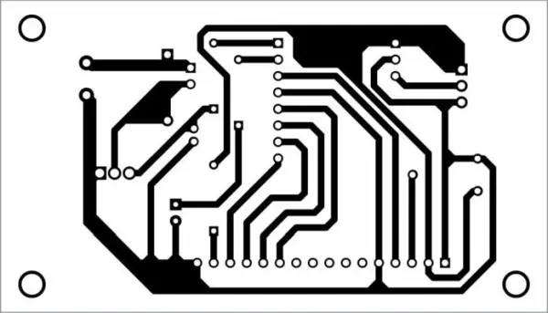
- PCB and component layout (traces, pads)
- Wiring for ADC and PWM connections
This project is an independent fan speed regulator that automatically adjusts the speed of an electric fan based on real-time feedback. The use of embedded system technologies like a microcontroller and closed-loop control architecture enables successful and reliable temperature regulation.
The ATMega8/168/328 microcontroller allows for rapid adjustment of fan speed based on real-time sensor information. An LCD screen improves ease of use by showing the temperature and fan speed simultaneously.
Despite being compact and straightforward, this controller has multiple uses beyond typical household fans. It can regulate different appliances like air conditioners, water heaters, ovens, furnaces, heat exchangers, incubators, and other devices to maintain optimal thermal conditions.
Using an automated feedback-controlled system instead of static fan setups helps reduce energy usage. This project demonstrates the ability of embedded systems to provide advanced control solutions in industries that require precise temperature regulation. Energy savings in different applications in the future could be accomplished through the utilization of comparable closed-loop designs.
Circuit and working
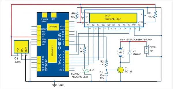
This standalone automated fan speed controller project changes the fan’s speed by utilizing feedback in real time. Effective and reliable temperature control is accomplished by using embedded system technologies like a microcontroller and closed-loop control architecture.
The ATMega8/168/328 microcontroller allows for rapid adjustments to fan speed based on real-time sensor readings. An LCD screen increases user-friendliness by showing the temperature and fan speed level simultaneously.
Even though it is compact and basic, this controller is suitable for more than just typical household fans. It can manage different equipment like air conditioners, water heaters, ovens, furnaces, heat exchangers, incubators, and other devices to maintain optimal thermal conditions.
Using an automated feedback-controlled system instead of fixed fan setups helps reduce energy usage. This project demonstrates how embedded systems can provide smarter control solutions in industries where temperature regulation is crucial. In the future, energy efficiency may be possible in different applications through the utilization of comparable closed-loop designs.
The temperature sensor LM35 measures the surrounding temperature and changes it into an analog electrical signal. The MCU on the Arduino board receives this signal via an analog-to-digital converter (ADC).
The MCU’s ADC is responsible for converting the analog temperature data into a digital format that can be interpreted by the Arduino’s code.
The LCD screen constantly shows the current fan speed setting and the digitized temperature values. This enables the monitoring of both metrics in real-time.
Utilizing the digital temperature data received, the MCU controls the motor driver circuit to regulate the fan speed accordingly. The motor driver module manages the fan motor’s power, enabling adjustable speed control through PWM signals from the Arduino.
In this manner, the Arduino MCU operates as the main processing center, overseeing the collection of temperature data through the ADC, computing and implementing necessary speed changes with the motor driver, and providing information on the LCD screen – achieving the full closed-loop temperature control function.
Fan speed control technique
The temperature sensor LM35 measures the surrounding temperature and changes it into an analog electrical signal. The MCU on the Arduino board receives this signal via an analog-to-digital converter (ADC).
The MCU’s ADC is responsible for converting the analog temperature data into a digital format that can be interpreted by the Arduino’s code.
The LCD screen constantly shows the current fan speed setting and the digitized temperature values. This enables the monitoring of both metrics in real-time.
Utilizing the digital temperature data received, the MCU controls the motor driver circuit to regulate the fan speed accordingly. The motor driver module manages the fan motor’s power, enabling adjustable speed control through PWM signals from the Arduino.
In this manner, the Arduino MCU operates as the main processing center, overseeing the collection of temperature data through the ADC, computing and implementing necessary speed changes with the motor driver, and providing information on the LCD screen – achieving the full closed-loop temperature control function.
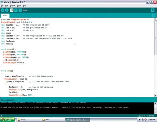
Construction and testing
The LM35 temperature sensor detects the ambient temperature and converts it to an analog electrical signal. The signal is sent to the MCU on the Arduino board through an analog-to-digital converter (ADC).
The ADC in the MCU converts the analog temperature data into a digital format for the Arduino’s code to read.
The LCD screen always displays the fan speed setting and temperature values in digital form. This allows for real-time monitoring of both indicators.
The MCU uses the received digital temperature data to adjust the fan speed by controlling the motor driver circuit. The fan motor’s power is controlled by the motor driver module, allowing for customizable speed adjustment using PWM signals from the Arduino.
This way, the Arduino MCU acts as the central processing unit, directing the temperature data collection via the ADC, making speed changes with the motor driver, and displaying information on the LCD screen to enable complete closed-loop temperature control.
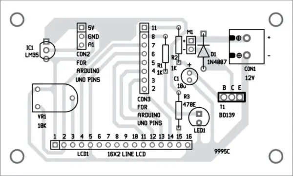
The circuit layout includes connectors CON2 and CON3 in order to connect Board1, the Arduino UNO microcontroller board, to external components using a organized interface.
A 12V battery powers the 12V DC fan motor. This enables the fan to function without being reliant on a main power source, resulting in a portable system that can be used for different purposes.
In conclusion, the connectors CON2 and CON3 connect the Arduino board to the remaining circuit components. At the same time, a 12V battery functions as the exclusive power supply for the 12V fan motor, which is controlled by the microcontroller and electronic control interface.
This setup allows for the division of various functional components while still maintaining complete closed-loop temperature control and feedback capabilities no matter where the portable system is used.
- How does the system measure temperature?
The LM35 temperature sensor measures ambient temperature and outputs an analog voltage corresponding to temperature. - How is the analog temperature converted for the controller?
The Arduino MCU uses its analog-to-digital converter ADC to digitize the LM35 analog signal for processing. - How does the controller adjust fan speed?
The MCU computes required speed changes from the digitized temperature and outputs PWM signals to the motor driver to regulate fan power. - What displays the temperature and fan speed?
An LCD screen continuously shows the current temperature and fan speed setting. - What powers the 12V fan motor?
A 12V battery supplies power to the 12V DC fan motor. - Can this controller be used for devices other than household fans?
Yes; the article states it can regulate devices like air conditioners, water heaters, ovens, furnaces, heat exchangers, and incubators. - What role do CON2 and CON3 connectors serve?
CON2 and CON3 connect Board1 (the Arduino UNO) to the external circuit components, organizing the interface. - What is the main processing unit of the system?
The Arduino MCU (ATMega8/168/328) serves as the central processor handling ADC, control logic, PWM output, and LCD updates.