This example shows how to read an analog input pin, map the result to a range from 0 to 255, and then use that result to set the pulsewidth modulation (PWM) of an output pin to dim or brighten an LED.
Circuit

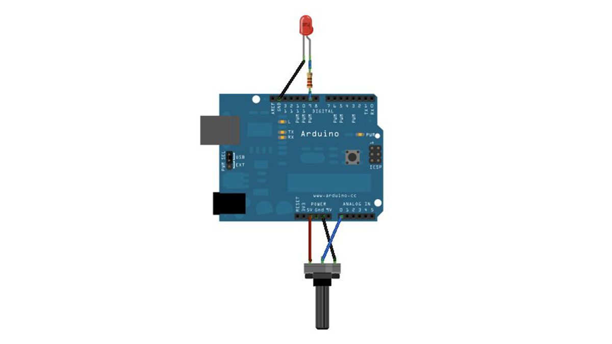
image developed using Fritzing. For more circuit examples, see the Fritzing project page
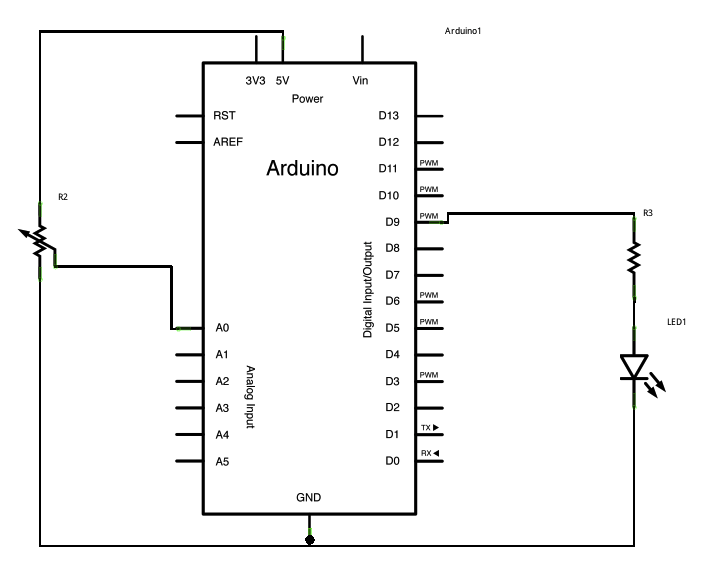
Connect one pin from your pot to 5V, the center pin to analog pin 0, and the remaining pin to ground. Next, connect a 220 ohm current limiting resistor to digital pin 9, with an LED in series. The long, positive leg (the anode) of the LED should be connected to the output from the resistor, with the shorter, negative leg (the cathode) connected to ground.
Schematic
Code
In the program below, after declaring two pin assignments (analog 0 for your potentiometer and digital 9 for your LED) and two variables, sensorValue and outputValue, the only thing that you do will in the setup function is to begin serial communication.
Next, in the main loop of the code, sensorValue is assigned to store the raw analog value coming in from the potentiometer. Because the Arduino has an analogRead resolution of 0-1023, and an analogWrite resolution of only 0-255, this raw data from the potentiometer needs to be scaled before using it to dim the LED.
In order to scale this value, use a function called map()
Hardware Required
- Arduino Board
- Potentiometer
- LED
- 220 ohm resistor
For more detail: Analog In, Out Serial using Arduino

