
Summary of RFID Door Lock With Arduino
This tutorial shows how to build an RFID-controlled door lock using an Arduino-compatible board and an RFIDuino shield. It covers reading tag IDs, programming accepted tags into a sketch, wiring a relay and solenoid or electronic strike, and mounting the reader and strike plate in a door frame. It warns about power-fail behavior differences between solenoids and normally-open strike plates and suggests keeping electronics indoors and the antenna weatherproofed.
Parts used in the RFID Door Lock:
- RFIDuino Shield and Antenna
- Geekduino or other Arduino compatible microcontroller
- RobotGeek Relay Board
- Door Latch Solenoid or Electronic Strike Plate (NO, normally open)
- 3-pin Sensor Cable
- 6v Power Supply for Geekduino
- Appropriate Power Supply for solenoid (example 12V)
- Micro USB cable for Geekduino or compatible cable for Arduino board
- Compatible RFID Tag
- Panel Mount Dual Power Cable
- Wire Nut, Electrical Tape, Solder, or other wire connection method
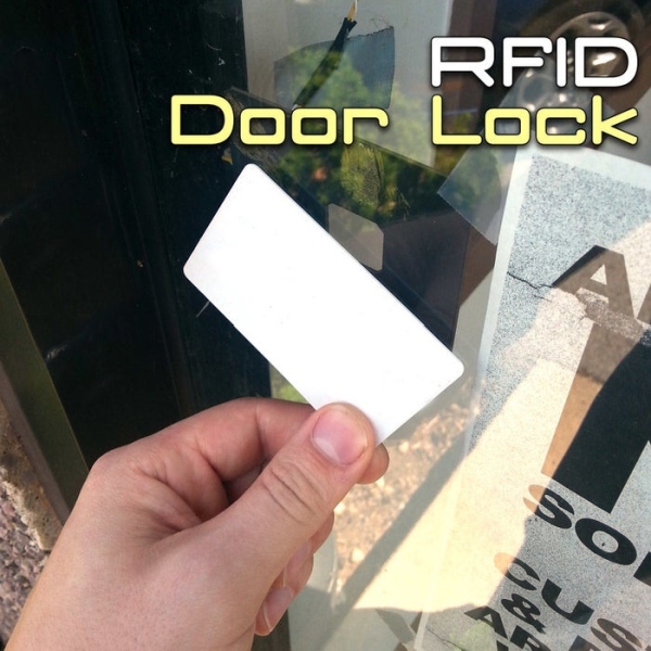
Here we are with the classic RFID door lock. It’s classic in that whole, “We live in the future and take it for granted at this point” sense. In this tutorial, we will set up a door latch that can be opened with the swipe of an RFID Tag! We will program a list of acceptable ‘key’ cards that will unlatch the door for a specified amount of time. This is a really simple project, but it does require that you alter your door jamb, so be prepared to do some wood work if you the strike plate to fit securely and flush.
Step 1: Project Parts List
These are the recommended parts for this project. You can use another Arduino variant, relay, or compatible RFID Tag, but we recommend using the RFIDuino Shield so that the code we will provide you in this tutorial works without a hitch.
- RFIDuino Shield and Antenna
- Geekduino or other Arduino compatible microcontroller
- RobotGeek Relay Board
- A Door Latch Solenoid or An Electronic Strike Plate (note that these are example parts, and may not fit your specific door. When selecting an electronic strike plate, make sure to choose one marked ‘NO’, or normally open. This means that when the circuit is open, the door is secured, keeping you safe in a power outage situation)
- 3-pin Sensor Cable
- 6v Power Supply (for Geekduino)
- An appropriate Power Supply for your solenoid (in the case of the linked solenoid, 12V)
- Micro USB cable for your Geekduino or cable for your Arduino compatible board
- A compatible RFID Tag -all tags on this page are compatible with the RFIDuino
- Panel Mount Dual Power Cable
- Wire Nut, Electrical Tape, Solder, or other wire connection method.
Note that using a straight door latch solenoid requires power to unlock the door. If you lose power, you will be effectively locked out and unable to open your door until power is returned to the system. With the electronic strike plate, you can still use your regular key to open the door in the case of a power outage. Choose wisely.
Step 2: Get Your RFID Tag Data
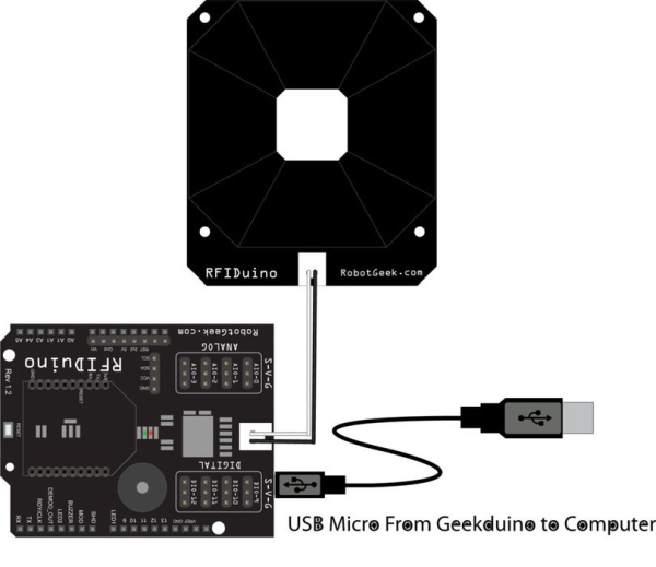
- Connect your RFIDuino as shown. (Click here for the v1.1 Connection Diagram)
- Open
RFIDuino_helloworldonto your board. You can find this sketch underFile>Examples>RFIDuino>RFIDuino_helloworld - You will need to make sure the code is adjusted for your RFIduino hardware.
v1.2 shields (2 pin antenna, ‘REV 1.2’ printed on the board) will need the following codeRFIDuino myRFIDuino(1.2); //initialize an RFIDuino object for hardware version 1.2v1.1 shields (4-pin antenna, no version number printed on the board) will need the following codeRFIDuino myRFIDuino(1.1); //initialize an RFIDuino object for hardware version 1.1Both lines of code are available in theRFIDuino_helloworldsketch, simply uncomment the one you don’t need.If you are still unsure about what hardware you are using, see this page - Connect a micro USB cable from your computer to your Geekduino
- Load RFIDuino_helloworld3 onto your board using the upload button in the Arduino IDE.
- Once loaded, you can leave your board connected to your computer – you will need this connection to power the board and to communicate with the computer
- Open the Serial Monitor.Tools -> Serial MonitorThe serial monitor should be set to its default settings (‘No Line ending’, 9600 baud)
- Swipe a tag across the RFIDuino antenna. The green light will light up and your buzzer will make a noise.
- The Serial Monitor will display 5 numbers. These numbers make up the ID of your tag.
- Copy down these numbers for future use. It can be handy to write the ID on a sticky note and attach it to the tag. NOTE: You will need the ID for at least one tag for the next step.
Step 3: Wiring and Programming
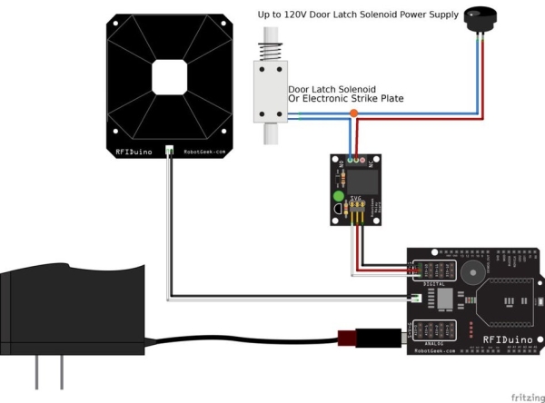
- Connect your components as shown here.
- Open
RFIDuino_demo3_lockbox_multionto your board. You can find this sketch underFile>Examples>RFIDuino>RFIDuino_demo3_lockbox_multi - You will need to make sure the code is adjusted for your RFIduino hardware.
v1.2 shields (2 pin antenna, ‘REV 1.2’ printed on the board) will need the following codeRFIDuino myRFIDuino(1.2); //initialize an RFIDuino object for hardware version 1.2v1.1 shields (4-pin antenna, no version number printed on the board) will need the following codeRFIDuino myRFIDuino(1.1); //initialize an RFIDuino object for hardware version 1.1Both lines of code are available in theRFIDuino_demo3_lockbox_multisketch, simply uncomment the one you don’t need.If you are still unsure about what hardware you are using, see this page. The RFID Experimenter’s Kit comes with the version 1.2 shield. - Modify the code for the number of cards you want by editing line 58. For example, if you have three cards, use the code#define NUMBER_OF_CARDS 3 //total numer of key cards that the system will respond to.
- You will also need to modify the sketch to include the IDs of the tags that you want to include. These IDs can be found using the
Hello Worldsketch. Find the block of code starting at line 62 – it looks like this.byte keyTag[NUMBER_OF_CARDS][5] ={ {0,0,0,0,0}, //Tag 1 //commenting each tag with a description can help you keep track of them {0,0,0,0,0}, //Tag 2 {0,0,0,0,0}, //Tag 3 {0,0,0,0,0},//Tag 4 }; Now insert the IDs for your tags. If we had three key tags, our code might look something likebyte keyTag[NUMBER_OF_CARDS][5] ={ {77,0,44,22,242}, //Tag 1 //commenting each tag with a description can help you keep track of them {200,1,4,98,236}, //Tag 2 {23,64,4,25,1}, //Tag 3 }; - Connect a micro USB cable from your computer to your Geekduino
- Load
RFIDuino_demo3_lockbox_multionto your board using the upload button int the Arduino IDE. - Once loaded, you disconnect the USB cable from your computer..
- Swipe any of the ‘key’ tags across the RFIDuino antenna. The green light will light up and your buzzer play three different notes. Additionally, the solenoid will fire.
- Swipe any tag that is not the ‘key’ tag across the RFIDuino antenna. The red light will light up and your buzzer play three monotone notes. The solenoid will not react.
Step 4: Mount It Where You Can Use It
Once you’re sure that you have it programmed and the latch releases when you swipe the correct RFID Tag, mount it in your door frame. We had a metal frame door with glass windows, so it was an easy call putting the RFID Reader behind the glass. You may want to mount the antenna in a weatherproof box for accessibility and keep the ~duino and other electronics indoors for safety.
There are instructions with the strike plate that should help you mount that. We recommend keeping the plate as flush as you can to the wall it’s mounted to, and to be careful when running wires through a wall.
Step 5: You’re Done!
That was fun! So now that you have an arduino that can let you into your home, what are you going to do next? You could add a keypad for code entry, that’d be pretty cool. What about integrating bluetooth, so you can unlock your door with your phone? There are loads of features you can add, and we’d love to see what you come up with!
Source: RFID Door Lock With Arduino
- What hardware is recommended to ensure the tutorial code works without modification?
The tutorial recommends using the RFIDuino Shield so the provided code works without a hitch. - How do I obtain the ID numbers for my RFID tags?
Load the RFIDuino_helloworld sketch, open the Serial Monitor at 9600 baud, swipe a tag, and copy the five numbers displayed. - How do I configure the sketch for my RFIDuino hardware version?
Uncomment RFIDuino myRFIDuino(1.2); for v1.2 shields or RFIDuino myRFIDuino(1.1); for v1.1 in the sketch. - How do I set the number of allowed key cards in the demo sketch?
Edit line 58 in RFIDuino_demo3_lockbox_multi to set #define NUMBER_OF_CARDS to the total number of key cards. - How are tag IDs inserted into the lock sketch?
Replace entries in the byte keyTag[NUMBER_OF_CARDS][5] array with the five-number IDs obtained from the Hello World sketch. - What happens when a valid tag is presented to the reader?
The green light lights, the buzzer plays three different notes, and the solenoid fires to unlatch the door. - What happens when an invalid tag is presented?
The red light lights, the buzzer plays three monotone notes, and the solenoid does not react. - Which type of strike plate is safer in a power outage?
Use an electronic strike plate marked NO (normally open) so the door remains secure and you can use a regular key during a power outage. - Where should I mount electronics and antenna?
Mount the antenna where accessible, possibly in a weatherproof box, and keep the Arduino and other electronics indoors for safety.
