Summary of Programmable Macropad V2
This Instructable shows building a 10-key, 4-state (up to 16 layouts possible) programmable macropad using an Arduino Pro Micro, diodes, and a click rotary encoder for volume and play/pause. It covers designing/printing a case, installing switches, LEDs and encoder, wiring a diode-protected key matrix, soldering, and Arduino code structure including separate layout functions and encoder handling.
Parts used in the Programmable Macropad V2:
- Key switches (11) and keycaps
- Arduino Pro Micro (1)
- Rotary encoder (1)
- IN4148 diodes (11)
- LEDs (4)
- 330 ohm resistor (1) or appropriate for LED color
- Wires
- USB cable
- Case (3D printed or other)
- Optional rubber feet
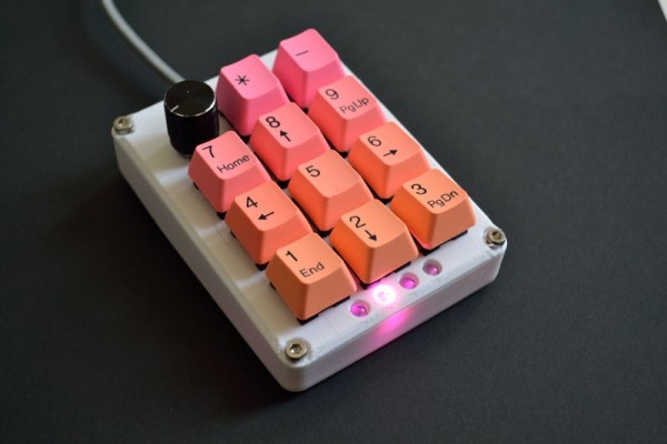
In this Instructable I will walk through how I build my new and improved Macropad. I made one a while back and it has always had some things I would like to improve on it. The main one being the location of the state LEDs. When redesigning the case I figured why not take a look at the whole thing and see if I can do a better job. So I did.
This macropad is capable of 10 buttons per layout and up to 16 layouts in total. If you can do it I’ll be impressed. It also has a click rotary encoder, that has a fixed function, volume and play/pause.
In this version I am sticking with an Arduino Pro Micro, and adding another button on. While I was reading I also decided to use diodes just like a really keyboard. This also makes coding a bit easier as a lot of libraries already exist for this.
I won’t spend a lot of time on why I made the changes I did, but I’ll touch on it here and there throughout. Honestly they both work great. I just wanted a new challenge.
Supplies:
Materials
I am providing links to what I used but don’t feel like you need these exact parts. Get, or use what makes sense for you.
(11) Key Switches & Caps (I used some I had, otherwise you could print some)
(1) Arduino Pro Micro
(1) Rotary Encoder
(11) IN4148 Diodes
Case & Hardware
(4) LEDs
(1) 330 ohm Resistor (or what ever size you need for the color you are using)
Wire
Optional:
Tools
- Soldering Iron
- Pliers
- Snips
- Wire strippers
- Scissors
- 3D printer (optional)
Step 1: Case
As with any project I like to get the case started first. Especially when printing one, as it takes a while and I only need to slice and load the file and the printer does the rest. Here is a link to the case that I designed for this project: https://www.thingiverse.com/thing:4792978
This project does necessitate the at least the top of the case being done before moving on as all of the parts need to be clipped into the top and then soldered together.
You don’t need to print a case for this. You can use what ever you have access too.
For this case design I would recommend checking the dimensions on your keys, LEDs, and encoder before printing the whole thing.
Step 2: Assemble the Top
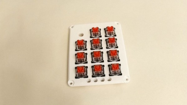
The begins by installing all the switches into the plate. The best fit on the switches is a bit tight, that way you can remove any key caps and the switch won’t pull out.
After adding the switches bend the ground leg of the LED down at a right angle and place them into their spots at the bottom of the plate with the bend leg on the outside.
If your encoder came with header pins, like mine did, you will need to remove them before you can put the encoder in place as the pins run into the switches. To do that use your snips to clip the plastic that holds them all together and then remove them one at a time using a soldering iron to heat the pin and solder and a pair of pliers to pull the pin out. Once the pins have been removed you can put the encoder in place and attach it. It may also be easier to wait until you have soldered the wires onto the encoder before putting it in place.
Step 3: Soldering
Soldering this is the hardest part.
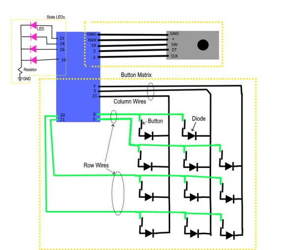
Each of the switches needs a diode and a wire. We are basically making a grid wires with a switch and diode at each intersection. The diodes help in case more than one switch is pressed at a time. I’ve attached a circuit layout that I used (or pretty close). The pins aren’t hugely important, as they can easily be swapped in the code later. Make sure that you avoid pin 0 and 1 (RX and TX) as I think they are used to communicate with the computer; tying into them might be weird.
There are 3 pins that are important. They are the pins from the encoder. The encoder will work best if the moment tracking pins connected to interrupt capable pins on the Micro. On the Pro Micro attached to pin 2 and 3. They are important as they track the movement of the encoder. If you have the same encoder I do they are the DT and CLK pins. The encoder I have also needs +5v to work, so the power needs to run from the RAW pin. The RAW pin exposes the +5v coming from the USB port. All other pins will run at 3.3v.
Step 4: Code
Now the fun part. For this version I am breaking the code down into a lot more functions. Functions are useful as the make it a lot easier to keep each section of your code small. By making each section smaller, its easier to follow.
The main thing to remember with functions is that each function should only do 1 thing. The other thing to remember is why write code many times when you can wrap it in a function and use it a bunch of times.
I’ve attached the code below and if you are interested I have an in depth walk through in the next step.
For the actual key functions I’ve left a few in Layout2() for you to look at. With this code always remember when sending key strokes make sure that you release any keys you press. Some of the functions like .send() do release the keys they press but .press() does not. Use .releaseAll() to release pressed keys.
You can change the pin numbers at the top to what you have used.
#include <Keypad.h>
#include <Encoder.h>
#include <Bounce2.h>
#include "HID-Project.h"
//Keypad buttons
int R1 = 6;
int R2 = 5;
int R3 = 21;
int R4 = 20;
int C1 = 7;
int C2 = 8;
int C3 = 9;
const byte ROWS = 4;
const byte COLS = 3;
char keys[COLS][ROWS] = {
  {'X','7','4','1'},
  {'*','8','5','2'},
  {'-','9','6','3'}
};
byte rowPins[ROWS] = {R1, R2, R3, R4};
byte colPins[COLS] = {C1, C2, C3};
Keypad kpd = Keypad( makeKeymap(keys), colPins, rowPins, COLS, ROWS);

//State LED pins
int S1 = 15;
int S2 = 14;
int S3 = 16;
int S4 = 10;
const int numStates = 4;
const int States[numStates] = {S1, S2, S3, S4};
int currentState = 0;

int lastDebounceTime = 0;
const int debounceTime = 50;

//Encoder
int SW = 19;
int DT = 2;
int CLK = 3;
Encoder volumeKnob(DT,CLK);
Bounce encoderButton = Bounce(SW,10);
int timeLimit = 500;
long oldPosition = -999;

void setup() {
  // put your setup code here, to run once:
  Serial.begin(9600);

  for (int i = 0; i < numStates; i++){
    pinMode(States[i], OUTPUT);
    digitalWrite(States[i], LOW);
  }

  pinMode(CLK, INPUT_PULLUP);

  Keyboard.begin();
  //Consumer.begin();

  Serial.print("Ready");

  StartAnimation();
  digitalWrite(States[currentState], HIGH);
}

void StartAnimation(){
  int waitTime = 250;
  digitalWrite(S1, HIGH);
  delay(waitTime);
  digitalWrite(S2, HIGH);
  delay(waitTime);
  digitalWrite(S3, HIGH);
  delay(waitTime);
  digitalWrite(S4, HIGH);
  delay(waitTime);
  digitalWrite(S1, LOW);
  delay(waitTime);
  digitalWrite(S2, LOW);
  delay(waitTime);
  digitalWrite(S3, LOW);
  delay(waitTime);
  digitalWrite(S4, LOW);
  delay(waitTime);
  return;
}

void ChangeState(){
  digitalWrite(States[currentState], LOW);
  currentState++;
  if (currentState == numStates){
    currentState = 0;
  }
  digitalWrite(States[currentState], HIGH);
  //Serial.print("State Changed. Current State: "); Serial.println(currentState);
  delay(100);
  return;
}

void Layout1(char button){
  switch(button){
    case '1':
      Keyboard.print('1');
      break;
    case '2':
      Keyboard.print('2');
      break;
    case '3':
      Keyboard.print('3');
      break;
    case '4':
      Keyboard.print('4');
      break;
    case '5':
      Keyboard.print('5');
      break;
    case '6':
      Keyboard.print('6');
      break;
    case '7':
      Keyboard.print('7');
      break;
    case '8':
      Keyboard.print('8');
      break;
    case '9':
      Keyboard.print('9');
      break;
  };
}//
void Layout2(char button){
  switch(button){
    case '1'://
      break;
    case '2'://
      break;
    case '3'://
      break;
    case '4'://
      break;
    case '5'://
      break;
    case '6'://Return
      Keyboard.press(KEY_RETURN);
      Keyboard.releaseAll();
      break;
    case '7'://Escape
      Keyboard.press(KEY_ESC);
      Keyboard.releaseAll();
      break;
    case '8'://
      break;
    case '9'://
      break;
  };
}

void Layout3(char button){
  switch(button){
    case '1':
      Keyboard.print('7');
      break;
    case '2':
      Keyboard.print('8');
      break;
    case '3':
      Keyboard.print('9');
      break;
    case '4':
      Keyboard.print('4');
      break;
    case '5':
      Keyboard.print('5');
      break;
    case '6':
      Keyboard.print('6');
      break;
    case '7':
      Keyboard.print('1');
      break;
    case '8':
      Keyboard.print('2');
      break;
    case '9':
      Keyboard.print('3');
      break;
  };
}

void Layout4(char button){
  switch(button){
    case '1':
      Keyboard.print('1');
      break;
    case '2':
      Keyboard.print('2');
      break;
    case '3':
      Keyboard.print('3');
      break;
    case '4':
      Keyboard.print('4');
      break;
    case '5':
      Keyboard.print('5');
      break;
    case '6':
      Keyboard.print('6');
      break;
    case '7':
      Keyboard.print('7');
      break;
    case '8':
      Keyboard.print('8');
      break;
    case '9':
      Keyboard.print('9');
      break;
  };
}

void loop() {
  //check the key matrix first
  char key = kpd.getKey();
  if(key) {
    switch(key){
      case '*':
        ChangeState();
        break;
      case '-':
        Keyboard.press(KEY_RIGHT_CTRL);
        Keyboard.press('s');
        delay(10);
        Keyboard.releaseAll();
        break;
      default:
        switch(currentState){
          case 0:
            Layout1(key);
            break;
          case 1:
            Layout2(key);
            break;
          case 2:
            Layout3(key);
            break;
          case 3:
            Layout4(key);
            break;
        }
    }
  }

  //check the encoder button
  if(encoderButton.update()) {
    if(encoderButton.fallingEdge()) {
      int fall = millis();
      while(!encoderButton.update()){}
      if(encoderButton.risingEdge()){
        int rise = millis();
        //Serial.println(rise - fall);
        if(rise - fall > timeLimit){
          Consumer.write(MEDIA_NEXT);
          Serial.print("Next");
        } else {
          Consumer.write(MEDIA_PLAY_PAUSE);
          Serial.print("Play/Pause");
        }
      }
      Keyboard.releaseAll();
    }
  }

  //check encoder rotation
  long newPosition = volumeKnob.read();
  if(newPosition != oldPosition){
    Serial.print(newPosition);

    if((newPosition - oldPosition) > 0) {
      //volumeup
      Serial.println("volume up");
      Consumer.write(MEDIA_VOLUME_UP);
    } else {
      //volumedown
      Serial.println("volume down");
      Consumer.write(MEDIA_VOLUME_DOWN);
    }
    oldPosition = newPosition;
    Keyboard.releaseAll();
    delay(200); //a delay of 200 seems to be the sweet spot for this encoder.
  }
}
Source: Programmable Macropad V2
- How many buttons and layouts does the macropad support?
The macropad is capable of 10 buttons per layout and up to 16 layouts in total. - Can I use an Arduino Pro Micro for this project?
Yes, this version sticks with an Arduino Pro Micro. - Do I need diodes for the key switches?
Yes, the build uses IN4148 diodes for each switch to prevent ghosting. - What does the rotary encoder control?
The click rotary encoder controls volume (rotation) and play/pause or next track (press/long press). - Which pins are important for the encoder on the Pro Micro?
The encoder moment tracking pins (DT and CLK) should be connected to interrupt-capable pins, on the Pro Micro they used pins 2 and 3, and the encoder power runs from RAW for +5V. - Are there recommended tools for assembly?
Yes; soldering iron, pliers, snips, wire strippers, scissors, and optionally a 3D printer. - Do I have to 3D print the provided case?
No, you can use any case you have access to, but the provided Thingiverse case is recommended for this design. - What libraries are used in the provided code?
The code uses Keypad, Encoder, Bounce2, and HID-Project libraries. - How does the code handle multiple layouts?
The code defines separate Layout1, Layout2, Layout3, and Layout4 functions and switches behavior based on currentState. - How are state LEDs managed?
Four state LED pins are defined and controlled to indicate currentState, with an initial StartAnimation sequence in setup.