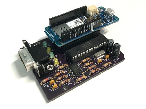
ObdiiUartMkrShield is a socket board for Arduino MKR board to talk with vehicles through ODB-II interface.
Things used in this project
Story
Background
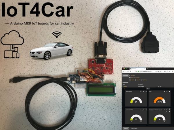
Previously, I published a blog of “IoT4Car” demonstrating how to collect the vehicle data using a SparkFun OBD-II UART board and an Arduino MKR1000 board, and uploading the data into clouds for real-time monitoring. That prototype was made on a breadboard with a lot of wires, which makes it vulnerable to vibrations and bad contact. So I decided to make a customized PCB board, so called ObdiiUartMkrShield, that has similar functionalities but compatible to Arduino MKR board form factor and IO voltage tolerance.
Design Flow
On-board diagnostics (OBD) is an automotive term referring to a vehicle’s self-diagnostic and reporting capability. Up till now, OBD has evolved to OBD-II standard with 16 pins interface. 5 signaling protocols are permitted in the OBD-II interface, being SAE J1850 PWM, SAE J1850 VPW, ISO 9141-2, ISO 14230 KWP2000, and ISO 15765 CAN. To simply the design, this PCB only supports Controller Area Network (CAN) protocol.
The communication between an Arduino board and a vehicle is realized by two chips. MCP2551 is used as the interface between a CAN physical layer and a CAN protocol controller. STN1110 is a multiprotocol OBD to UART interpreter that supports all 5 protocols. Here we only use its CAN protocol translation functionality. The schematics of the connection is shown in the attachment.
Though both chip datasheets provide sample circuit schematics, It is worth noting that selection of the capacitors for the crystal is critical. Differential crystal may have different cap loading. Selecting wrong cap values will result in different oscillation frequency, and thus the communication between STN1110 and MCP2551 will fail. Adafruit has a good tutorial of how to calculate the value of the capacitors that attach to the crystal. A general rule of thumb is C1, C2 = 2*CL – 2*Cstray, where CL is the crystal’s load capacitance, Cstray is the parasitic capacitance and is approximately 2-5 pF.
PCB Design
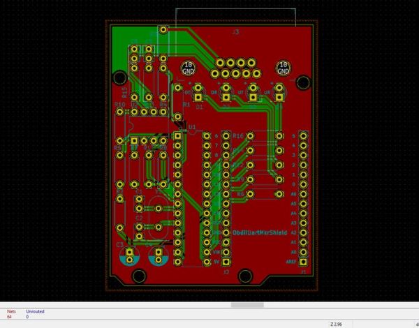
The PCB layout is implement in KiCAD, which has no limitation on board size or number of connections. The schematic can be found in the attachment. Below is a screenshot of the layout.
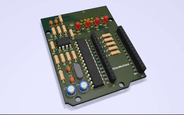
The 3D model is rendered by raytracing engine in KiCAD.
Assembly
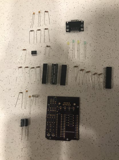
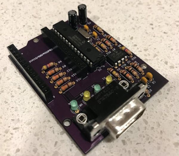
The PCB was fabricated by OSHpark. It usually takes 10 days to fab, and a few more days for shipping. After get the boards back, and purchasing the required components, the device is ready to be assembled. For a hobbyist like me, I usually choose through hole components because they are easy to solder. Electrical engineer veterans and professionals should use SMT components because they are cheaper.
Test
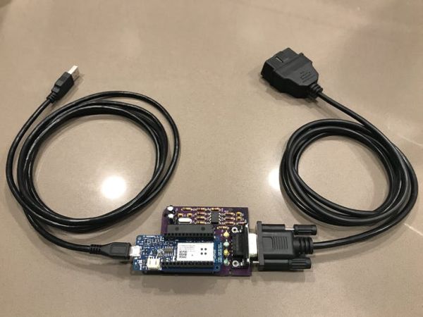
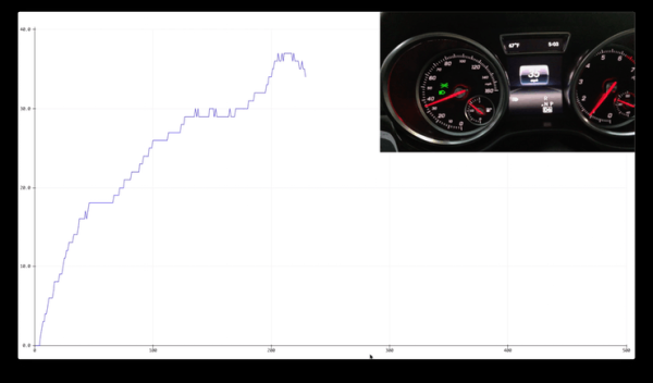
To test the ObdiiUartMkrShield PCB board, I wrote a program that can collect the car speed, and uploaded the code in an Arduino MKR1000 board. The program is available in the attachment. The car speed will be collected and plotted on the screen. Place the ObdiiUartMkrShield PCB under the Arduino MKR1000 as a socket, and connect the PCB with a DB9 to OBD-II cable. The OBD-II connector will be plugged into the car.
Here is a simple demo video. After introduction, you will see the comparison of car speed from the car dashboard and the Arduino serial plotter.
Schematics
Code
Source : IoT4Car (2)


_4YUDWziWQ8.png?auto=compress%2Cformat&w=48&h=48&fit=fill&bg=ffffff)
