Summary of LED POV CLOCK ARDUINO PRO MINI
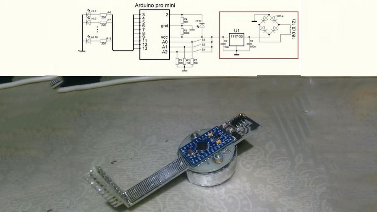
This Arduino LED POV clock project creates a holographic display using an Arduino Pro Mini, a DS3231 real-time clock module, and a motor sourced from a PC motherboard. The system utilizes wireless energy transmission as an optional power method, though it can alternatively run on a battery connected to an AMS1117-3.3 regulator. The author designed the PCB using DipTrace software and provided source code for operation.
Parts used in the Arduino LED POV Clock:
- Arduino Pro Mini
- DS3231 Real Time Clock Module
- Motor (Disassembled from PC motherboard)
- Wireless Energy Transmission Circuit
- AMS1117-3.3 Voltage Regulator
- Battery (Optional Power Source)
- NE555 Timer
- DipTrace Software (for PCB drawing)
- Arduino Board Inserted PCB
The Arduino led pov clock circuit has been an interesting project, and the author has made use of the arduino feeding system with the popular wireless energy transmission method, which is an additional circuit…Electronics Projects, Led Pov Clock Arduino Pro Mini “arduino projects, led projects, microcontroller projects, “
The Arduino led pov clock circuit has been an interesting project, and the author has made use of the arduino feeding system with the popular wireless energy transmission method, which is an additional circuit for additional NE555.
But if you do not want to deal with the wireless power supply for the Arduino Pro Mini, you can use the battery at the input of the 3.3v regulator (AMS1117-3.3) used at the inlet of the wireless energy circuit making it a bit troublesome coil winding can be troublesome
Real time clock, DS3231 module used for RTC Mainboard part motor used for writing in the air Motor motherboard Disassembled from PC motherboard Arduino board inserted PCB drawing DipTrace prepared Arduino Pro source code and pcb drawing files
ARDUINO LED POV CLOCK CIRCUIT DIAGRAM
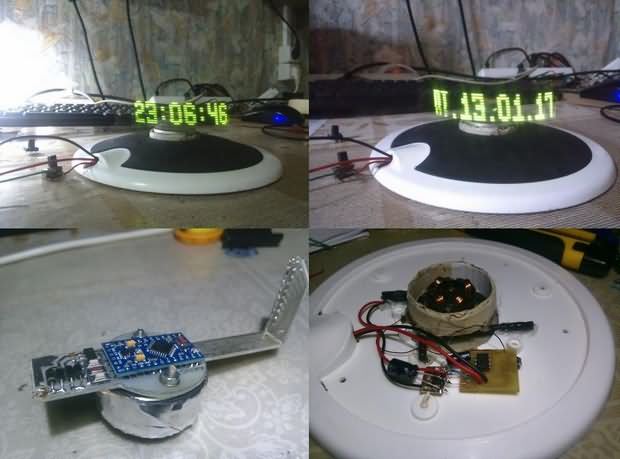
ARDUINO HOLOGRAPHIC CLOCK WORK
Source: https://goo.gl/VNE3FG
- How is the power supply managed in this project?
The project uses wireless energy transmission with an additional NE555 circuit or a battery feeding into an AMS1117-3.3 regulator. - What component provides the real-time clock function?
A DS3231 module is used as the RTC Mainboard part. - Where does the motor come from?
The motor is disassembled from a PC motherboard. - Can I avoid winding coils for the power supply?
Yes, you can use a battery at the input of the 3.3v regulator instead of dealing with the wireless power supply coil winding. - Which software was used to prepare the PCB drawing?
The PCB drawing was prepared using DipTrace software. - Is there source code available for the project?
Yes, Arduino Pro source code and PCB drawing files are included in the project description. - What type of display technology does this circuit utilize?
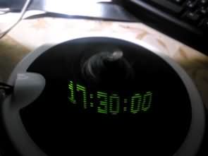
The circuit utilizes a Persistence of Vision (POV) method to write images in the air.