Summary of DIY: Measuring Wheel/Surveyor’s Wheel Using Arduino & Rotary Encoder
DIY Measuring Wheel/Surveyor’s Wheel Using Arduino & Rotary Encoder — concise summary: A digital surveyor’s wheel uses a rotary encoder mounted to the wheel to count rotations and angles. An Arduino Nano reads encoder pulses on D2 and D3, determines rotation and direction, converts counts to distance via calibration, and displays the measured distance in centimeters on a 16x2 LCD. The LCD is wired to Arduino pins D0–D5 with a contrast preset and backlight; power comes from a 9V battery to Vin via a switch.
Parts used in the Measuring Wheel/Surveyor’s Wheel:
- Arduino Nano
- Rotary encoder (with OUT1, OUT2, and common/GND)
- 16x2 LCD module
- Preset (potentiometer) for LCD contrast
- 9-volt battery
- Switch for battery power
- Wiring/jumper wires
- Mounting wheel and mechanical coupling for encoder
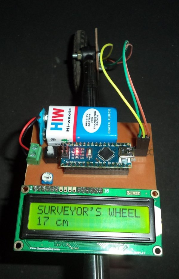
DIY: Measuring Wheel/Surveyor’s Wheel Using Arduino & Rotary Encoder
A surveyor’s wheel may also be known by other names like: clickwheel, hodometer, waywiser, trundle wheel, measuring wheel or a perambulator. All these devices serve a single purpose, which is, measuring distance.
The origin of surveyor’s Wheel is from an odometer. Odometer simply counts the number of rotations of the wheel. The distance travelled by the wheel is directly proportional to the radius of wheel.
In the digital Surveyor’s Wheel a rotary encoder is attached to the wheel. This rotary encoder precisely counts the number of rotations. It also counts the rotation angle, and hence the digital system is much more precise then mechanical system.
An Arduino Nano is used as the controlling unit. It reads the pulses coming from the rotary encoder and calculates the traveled distance and prints on LCD (Liquid Crystal Display).
Working
When the Rotary encoder rotates, it sends the pulses to Arduino. Output pins of the rotary encoder are connected to pin D2 and pin D3 of Arduino. Arduino identifies the rotation and direction (clockwise or anticlockwise) of the wheel. Arduino counts the pulses and converts them in distance by using some basic mathematical operations, called calibration. Now calculated distance is shown on the LCD.
Rotary encoder
In the rotary encoder spaced conductors are placed on a disc and connected to common pin. Encoder have two output pins (OUT1 and OUT2), When encoder rotates, output pins gives ZERO and ONE. The pattern of ZERO and ONE in OUT1 and OUT2 helps in determination of direction and rotation.
Arduino
Arduino is the brain of the whole project which counts the rotation. Arduino converts the rotation into distance using calibration and displays the information on LCD.
LCD
LCD (Liquid Crystal Display) is the output device; it shows the measured distance in Centimeter.
In this project, we are using 16×2 LCD (16 Columns and 2 Rows). The LCD has 16 pins, some pins are power pins, and 6 pins are connected to Arduino and two pins are used for backlight. A preset is also connected to 3rd pin of LCD which is used for contrast control of the LCD.
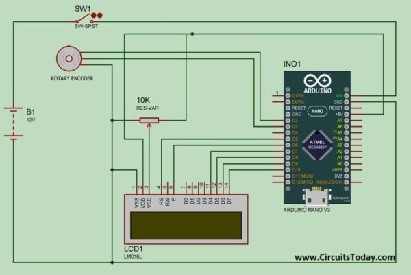
Circuit
In the circuit Arduino, LCD and Rotary Encoder are the main components. Rotary encoder has three pins. One pin is connected to GND and two pins are connected to D2 and D3 pins of Arduino. LCD is connected to Arduino through pins D0 to D5. Vin pin of Arduino is powered by a 9-volt battery through a switch.
Read more: DIY: Measuring Wheel/Surveyor’s Wheel Using Arduino & Rotary Encoder
- How does the rotary encoder help measure distance?
The rotary encoder outputs pulse patterns on its two output pins that Arduino counts to determine rotations and angle, which are converted to distance. - Which Arduino pins read the rotary encoder outputs?
The encoder outputs are connected to Arduino pins D2 and D3. - How is direction of wheel rotation determined?
Arduino reads the pattern of zeros and ones from the encoder outputs to identify clockwise or anticlockwise direction. - How is the measured distance displayed?
Calculated distance is shown on a 16x2 LCD in centimeters. - Which Arduino pins connect to the LCD?
The LCD is connected to Arduino through pins D0 to D5. - How is the LCD contrast adjusted?
A preset (potentiometer) is connected to the LCD third pin for contrast control. - What powers the Arduino in this project?
The Arduino Vin pin is powered by a 9-volt battery through a switch. - What advantage does a digital surveyor’s wheel have over a mechanical one?
The digital system with a rotary encoder is much more precise because it counts rotations and rotation angle electronically.