Summary of LM317 Voltage Regulator in Proteus
This article explains designing a variable DC power supply using the LM317 voltage regulator in Proteus ISIS. It demonstrates how to control a DC motor's speed and monitor voltage by adjusting a potentiometer connected to the LM317 IC. The project highlights the regulator's utility for powering various microcontrollers like Arduino or XBee with adjustable voltages ranging from low levels up to nearly 12V.
Parts used in the LM317 Voltage Regulator Circuit:
- LM317k Voltage Regulator IC
- Variable Resistor (Potentiometer)
- DC Motor
- Voltmeter
- LED
- 12-Volt DC Supply
Hello friends, hope you all are fine and having fun. In today’s post we are gonna have a look at LM317 Voltage Regulator in Proteus. In the previous post, we have seen how to design a 5V Power Supply in Proteus ISIS, which I have designed using IC regulator 7805. Today I am going to share How to design LM317 Voltage Regulator Circuit in Proteus. This DC power supply is a variable one means you can set its output voltage to any level you want. In order to change its output value we have used a variable resistor and by changing its value you can change the output value. It is a basic level project and very simple but used as a base to design large industrial projects. In this project, we are going to control the speed of a DC Motor and the corresponding voltages, appearing across it. The reason for designing this variable DC power supply is that, when you are working on some engineering project then each electronic module has its own power level i.e. xbee module works on 3.3V while Arduino board works on 5V. So, there’s a need to design such power supply which can provide variable voltages and we can set them according to our demand. So, for all Microcontrollers like Arduino or PIC Microcontroller or 8051 Microcontroller, I designed 5V Power supply using 7805 but for 3.3V modules like XBee, NRF24L01 etc I design this variable DC power supply using LM317. I hope now you got the importance of this LM317 Voltage Regulator.
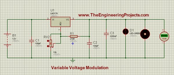
To design this, we will be using LM317k. Basically, it is a Voltage Regulator IC. It has 3 pins. Pin # 2 is for input voltages, marked as VI. Pin # 3 is for output voltages, marked as VO, and pin # 1 is used for Regulating Voltages and it is marked as ADJ. Further, if you notice the circuit diagram, which is given in the figure, then you will see that pin # 1 is connected to a Potentiometer. Potentiometer is a Variable Resistor device and it is also known as Voltage Divider. The feature of this electronic device is that, we can adjust the voltage through it according to our own choice. It operates on 12 Volts and it gives us ease that, we can adjust its voltages from 0 to MAXIMUM (which is 12 volts in most cases). Further if we notice the circuit, then we will see that a LED is connected in parallel with a simple DC motor and a voltmeter is also connected in parallel with Motor to monitor the voltages appearing across it. Above information was a little demo about the individual components of the circuit, now let’s be practical and move towards Hardware and see how actually Electronic components respond. You should also have a look at Introduction to LM317, if you wanna read all the basics about it. So let’s get started with LM317 Voltage Regulator in Proteus:
LM317 Voltage Regulator in Proteus ISIS

- You can download this complete LM317 Voltage Regulator simulation by clicking the below button but I recommend you to design it on your own so that you learn most from it.
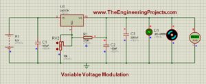
- First of all, place all the components in Proteus workspace, as shown in image:
- A 12-Volt DC supply is provided to input pin (# 2) of LM317 and potentiometer is connected to Adjustable pin of LM317, which is, pin # 1.
- At output pin we have connected DC Motor and a Voltmeter is also connected in parallel with Motor.
- The complete circuit, ready for simulation is shown below in image:
Stage # 1
- Set the potentiometer at 0% and run the simulation, you will notice that Motor will rotate very slowly in clock-wise direction and 1.25 volts will appear on the voltmeter across it. If all the connections are OK, and when you will run the simulation, LM317 Voltage Regulator simulation will look like as shown in the image below:

Note:
- If you don’t want to use the variable resistance, then you should use this LM317 Calculator to get value of your second resistance.
Stage # 2
- Now, set the potentiometer value to 11% and you will see that, Motor will start to rotate with a faster rate and on voltmeter scale, we will see 6.40 volts. In this setting, the interesting thing is, LED will start to Flash and it will turn ON & OFF automatically. This phenomenon can be seen in images below:
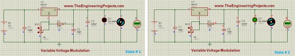
- Stage # 2 is our transient stage. When the potentiometers setting is below 11%, voltage appears across the motor and it also rotates but LED doesn’t glow. On the other hand, when potentiometers setting is above 11%, then LED glows continuously while motor also rotates as before, and voltmeter also gives some particular values of voltages appearing across the motor.
Stage # 3
- Now at final stage, set potentiometer to 100% and you will observe that motor is rotating with full speed and voltmeter reading will be 10.6 volts while LED is glowing continuously. This stage of the simulation can be seen in the image below:
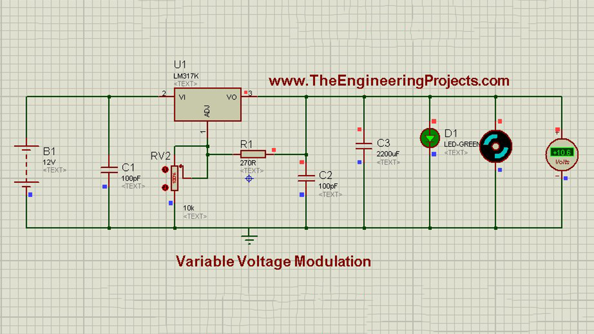
Now, we can conclude that, LM317 is the monitoring device of this circuit. We can set the value of potentiometer according to our own choice and by this, the speed of motor can be controlled and also the corresponding voltages, appearing across it.
Here’s the video in which I have given the detailed introduction of LM317 and have also run its simulation:
Alright friends, that’s all for today and I hope now you can easily design this LM317 Voltage Regulator. In the next post, I have discussed DC Motor Drive circuit in Proteus ISIS . Till than take care and be safe !!! ?
- What is the primary function of the LM317 circuit described?
It acts as a variable DC power supply allowing users to set output voltage to any level. - How can the output voltage be changed in this project?
The output value is changed by adjusting the value of a variable resistor or potentiometer. - Which pins are used on the LM317k IC?
Pin #2 is for input voltage, Pin #3 is for output voltage, and Pin #1 is for regulating voltage. - What happens to the LED when the potentiometer is set below 11%?
The LED does not glow when the potentiometer setting is below 11%. - At what potentiometer setting does the LED start flashing automatically?
The LED starts to flash and turn ON and OFF automatically at an 11% setting. - What is the voltmeter reading when the potentiometer is set to 100%?
The voltmeter reading will be 10.6 volts when the potentiometer is set to 100%. - Why is a variable DC power supply needed for modules like XBee?
Modules like XBee require specific power levels like 3.3V, which a fixed supply cannot provide. - What is the recommended approach for learning this circuit design?
The author recommends designing the circuit on your own rather than just downloading the simulation.