
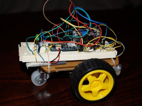
Summary of Wi-Fi RC Car – Qi Enabled
This project demonstrates building a Wi-Fi controlled RC car capable of wireless recharging. The Arduino MKR1000 serves as the brain, connecting via Wi-Fi to a mobile device for control through a web interface. It features two speed modes and uses an L293DNE motor driver powered by a boosted 5V output from a 3.7V Li-Po battery. When parked over a Qi transmitter, the IDT receiver automatically charges the battery without physical connectors.
Parts used in the Wi-Fi Controlled RC Car with Wireless Charging:
- IDT Qi 5W Transmitter Prototype Kit
- IDT Qi 5W Receiver Prototype Kit
- Arduino MKR1000
- 2WD Robot Car Chassis for Arduino
- L293DNE Motor Driver
- CN6009 Step-up boost Power Converter Module
- 3.7V Li-Po Battery
- 1N4007 Diode
- Generic LED
- 221 ohm Resistor
- Tie Wraps
- Generic Breadboard
This is a project that will show you how to create a Wi-Fi controlled RC Car that will recharge wirelessly while it is parked.
Things used in this project
Hardware components |
||||||
 |
|
× | 1 | |||
|
|
× | 1 | |||
|
|
× | 1 | |||
|
× | 1 | ||||
|
× | 1 | ||||
|
× | 1 | ||||
|
× | 1 | ||||
|
|
× | 8 | |||
|
|
× | 1 | |||
|
|
× | 1 | |||
|
× | 5 | ||||
|
|
× | 1 | |||
Software apps and online services |
||||||
|
|
|||||
Hand tools and fabrication machines |
||||||
|
|
|||||
|
|
|||||
|
||||||
|
||||||
Story
What will you Build in this Project?
This is a project that will show you step by step how to create a Wi-Fi controlled RC Car that will automatically recharge wirelessly while it is parked.
How it works?
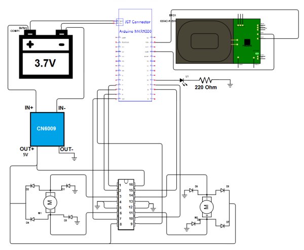
The brain of the project is the Arduino MKR1000 and it is connected through Wi-Fi with your mobile device. The Arduino board is powered by a 3.7V Li-Po battery. For the motor control an L293DNE motor driver is used. However it needs at least 4.5V to operate. We will step up voltage from 3.7V to 5V with a Step-up boost Power Converter Module (converts low voltage to higher) and in this way the motor driver will be powered with 5V.
For charging the battery, the Arduino MKR1000 board features an automatic charging system for Li-Po batteries. When an external source (5V DC) of power is connected, the battery that is connected to the board is being charged. So the IDT P9025AC-R-EVK – Qi 5W Receiver will be connected to the Arduino board as an external source (5V DC). When the car parks over the charging station (which is the IDT P9038-R-EVK – Qi 5W Transmitter), the battery will charge.
The control system features two speed modes: Fast and Slow.
How to build it?
Hardware Part
Solder wires on the motor poles and on the IDT Receiver board (Pin OUT with red wire and pin GND with black wire). For this step you will need a soldering iron and 6 wires.

Making the electronic circuit. You can use a breadboard to create your circuit or else you can solder all the connections.
CAUTION: Use a 3.7V Li-Po battery with at least 700mAh capacity! Otherwise the battery may overheat and explode!
Adjusting the CN6009. Step-up power converter module to 5V. To adjust CN6009’s output value use a screwdriver. Be sure to check the output voltage (by connecting a Voltmeter to the pins OUT+ and OUT-).
Connecting the IDT wireless power Qi 5W receiver. Take a piece of plastic (e.g. plastic card) to make a base for the Wireless Power Receiver on the bottom of the car. Then glue the piece of plastic as well as the Receiver to the bottom of the car with silicone. Finally, connect the red wire of the IDT Receiver to the VIN pin of the arduino and the black wire to the GND pin.
Making the Vehicle Stable. Fasten with tie wraps the battery and the breadboard to the vehicle.
Software Part – Wi-Fi Connection
For this part just copy the code. In the code file fill in your network SSID and Password (lines 12, 13 in the code file). You need to follow the comment instructions. The code is currently set to work with WPA/WPA2 networks. If you want to connect to a WEP or an open network follow the instructions in the comments of the code (lines 34-37).

How to use it?
Step 1: Connecting to the Arduino MKR1000
Controlling the vehicle requires Wi-Fi connection. You can achieve that with two ways. The first one is to enable Wi-Fi Hotspot on your mobile device and connect the board to the Hotspot. The second one is to connect your mobile device and the Arduino board to the same Wi-Fi router. Be sure to fill in your router’s SSID and Password settings in the code file that will be uploaded to the Arduino board.
Note: It is better to use the first method (Wi-Fi Hotspot) because in this way you can control your vehicle without the need of a router.
Step 2: Getting the IP Address of the Arduino MKR1000
If the Arduino board is connected to the hotspot of your mobile device, go to Wi-Fi Hotspot settings and there you will see the IP address of your board (e.g. 192.168.1.1).
If the Arduino board is connected to a Wi-Fi router then you need to check that from the router settings.
The LED on the car indicates successful connection to the specified network and server activation.
Step 3: Accessing the Webserver of the Arduino MKR1000
Go to your browser and in the URL box type the IP address of your Arduino.
Step 4: Connecting the Charging Base
Connect the IDT P9038-R-EVK – Qi 5W Transmitter to a wall socket using a 5V DC Adapter.
Step 5: Have Fun!
Charging Time!!
Wireless Charging
UI
Test Drive:

Source : Wi-Fi RC Car – Qi Enabled
- How does the car recharge wirelessly?
The car parks over a Qi 5W Transmitter, allowing the connected Qi 5W Receiver to supply 5V DC power to charge the Li-Po battery. - Can I use any Li-Po battery for this project?
No, you must use a 3.7V Li-Po battery with at least 700mAh capacity to prevent overheating or explosion. - What is the best way to connect the Arduino board to the network?
It is better to enable a Wi-Fi Hotspot on your mobile device and connect the board to it, avoiding the need for a router. - Does the motor driver require the same voltage as the battery?
No, the L293DNE needs at least 4.5V, so a Step-up boost converter raises the 3.7V battery voltage to 5V. - How do I access the control interface for the car?
Type the IP address of the Arduino MKR1000 into your web browser after connecting to its network. - What speed modes are available for controlling the vehicle?
The system features two speed modes: Fast and Slow. - How can I verify the output voltage of the power converter?
You must use a voltmeter connected to the OUT+ and OUT- pins while adjusting the module with a screwdriver. - What happens if the car connects successfully to the server?
The LED on the car will light up to indicate successful connection and server activation.