Summary of Simple Arduino Digital Voltmeter
This article explains how to build a digital voltmeter using an Arduino Uno, a 16x2 LCD, and a voltage divider circuit. The project utilizes the Arduino's 10-bit ADC to measure DC voltages up to 55V by scaling them down with resistors. The measured voltage is displayed on the LCD and verified via the Serial Monitor and a multimeter.
Parts used in the Arduino Digital Voltmeter:
- Arduino uno
- 16x2 LCD (Liquid Crystal Display)
- 100 k ohm resistor
- 10 k ohm resistor
- 10 k ohm potentiometer
- breadboard
- jumper wires
With a simple knowledge of Arduino and Voltage Divider Circuit, we can turn the Arduino into Digital Voltmeter and can measure the input voltage using Arduino and a 16×2 LCD display.
Arduino has several analog input pins that connect to an Analog-to-Digital converter (ADC) inside the Arduino. The Arduino ADC is a ten-bit converter, means that the output value will range from 0 to 1023. We will obtain this value by using the analogRead() function. If you know the reference voltage you can easily calculate the voltage present at the analog input. We can use voltage divider circuit to calculate the input voltage. Learn more about ADC in Arduino here.
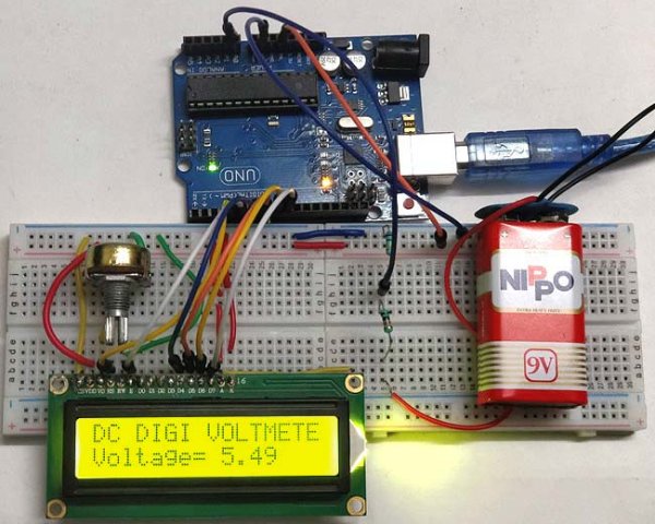
The voltage measured is displayed on the 16×2 Liquid Crystal Display (LCD). We have also displayed the voltage in Serial Monitor of Arduino IDE and confirmed the measured voltage using Multimeter.
Hardware Required:
- Arduino uno
- 16×2 LCD (Liquid Crystal Display)
- 100 k ohm resistor
- 10 k ohm resistor
- 10 k ohm potentiometer
- breadboard
- jumper wires
Voltage Divider Circuit:
Before entering into this Arduino Voltmeter circuit, lets discuss about the Voltage Divider Circuit.
Voltage divider is a resistive circuit and is shown in figure. In this resistive network we have two resistors. As shown in figure, R1 and R2 which are of 10k and 100k ohm. The midpoint of branch is taken to measurement as a anolog input to the Arduino. The voltage drop across R2 is called Vout , that’s the divided voltage of our circuit.
Formulae:
Using the known value (two resistor values R1, R2, and the input voltage), we can substitute in the equation below to calculate the output voltage.
Vout = Vin (R2/R1+R2)
This equation states that the output voltage is directly proportional to the input voltage and the ratio of R1 and R2.
By applying this equation in the Arduino code the input voltage can be easily derived. Arduino can only measure the DC input voltage of +55v, In other words, when measuring 55V, the Arduino analog pin will be at its maximum voltage of 5V so it is safe to measure within this limit. Here the resistors R2 and R1 value is set to 100000 and 10000 i.e. in the ratio of 100:10.
Circuit Diagram and Connections:
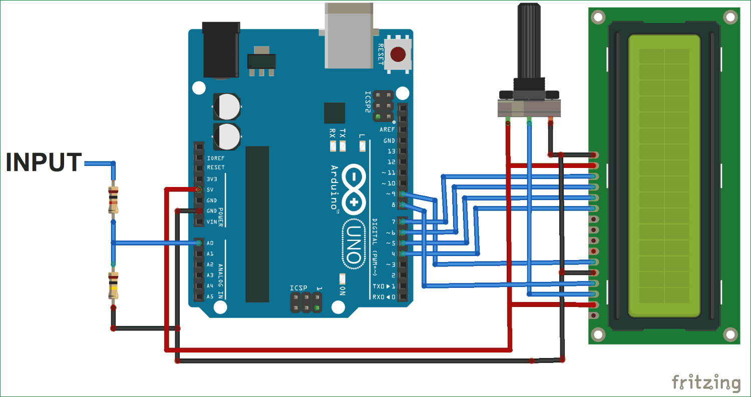
Connection for this Arduino Digital Voltmeter is simple and shown in the circuit diagram below:
Pin DB4, DB5, DB6, DB7, RS and EN of LCD are directly conneted to Pin D4, D5, D6, D7, D8, D9 of Arduino Uno
The Center point of two resistors R1 and R2, which makes the voltage divider circuit, is connected to Arduino Pin A0. While the other 2 ends are connected to the input volt (voltage to be measured) and gnd.
Read more: Simple Arduino Digital Voltmeter
- How does the Arduino measure input voltage?
The Arduino uses its analog input pins connected to a ten-bit Analog-to-Digital converter (ADC) to obtain values ranging from 0 to 1023. - What is the maximum DC voltage the Arduino can safely measure in this project?
The Arduino can only measure a DC input voltage of +55V, where the analog pin reaches its maximum safe voltage of 5V. - Which formula calculates the output voltage in the voltage divider circuit?
The formula used is Vout = Vin (R2/R1+R2), showing that output voltage is proportional to input voltage and the resistor ratio. - What is the role of the voltage divider circuit in this project?
The voltage divider circuit scales down high input voltages so they fall within the 0-5V range that the Arduino analog pin can read. - How are the LCD pins connected to the Arduino Uno?
Pin DB4, DB5, DB6, DB7, RS, and EN of the LCD are connected directly to Pin D4, D5, D6, D7, D8, and D9 of the Arduino Uno. - Where is the center point of the voltage divider connected?
The center point between resistors R1 and R2 is connected to Arduino Pin A0 for measurement. - Can the measured voltage be viewed outside the LCD?
Yes, the voltage is also displayed in the Serial Monitor of the Arduino IDE and confirmed using a Multimeter. - What function is used to read the analog value from the Arduino?
The analogRead() function is used to obtain the output value from the ADC.