
Summary of Spinduino – IoT Fidget Spinner
This article details the development of Spinduino, a programmable IoT fidget spinner featuring an RGB PoV display and BLE connectivity. The creator describes design iterations, including power management improvements and hardware fixes for a charge pump and antenna layout. Specific troubleshooting involved soldering capacitors directly to pins and adding pull-down resistors to prevent random LED flickering during sleep mode, ensuring stable operation with CR2032 batteries.
Parts used in the Spinduino:
- JavaScript
- 10-Pixel RGB PoV display (APA102 LEDs)
- Magnetic latch
- Nordic Semiconductor nRF52832 chip
- Bluetooth Low Energy (BLE)
- TPS60150 5V charge pump
- Hall effect sensors
- MC74VHC1GT125 Logic Level converter
- CR2032 batteries
Description
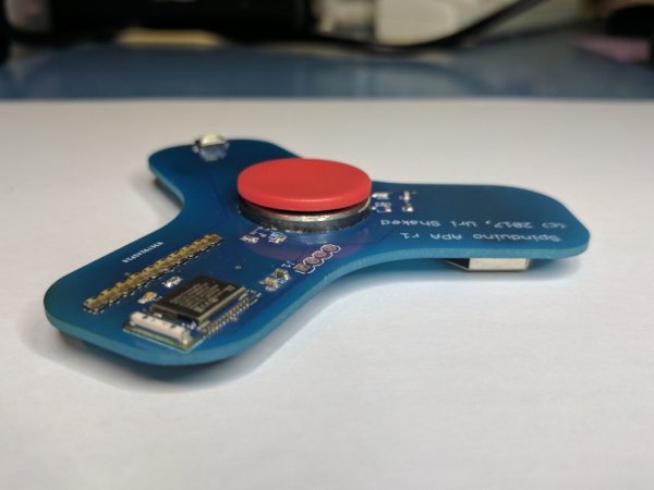
* JavaScript programmable
* 10-Pixel RGB PoV display (using APA102 LEDs)
* Spin count / speed detection using a magnetic latch
* Using Nordic Semiconductor nRF52832 chip
* Bluetooth Low Energy (BLE) communication with smart phone / computer for controlling the display, reading the spin count and programming
* Over-the-air firmware upgrades
* Fully open-source
They have several improvements over the first version:
- 5V charge pump for driving the LEDs (TPS60150)
- Power for LEDs and hall effect sensors controlled by the CPU
- Ground copper pour under the board
- Board is now truly symmetric – first version was slightly asymmetric
- Tighter grip of the bearing
These improvements give consistent light output from the LEDs, and enable saving power while the beacon in stand-by mode. The first prototype used about 15mA in standby (4mA by each hall-effect sensor, and another 7 mA by the LEDs), causing the CR2032 batteries to last only for a few hours.
Soldering the PCB and trying to run it revealed some issues with the new version. The most prominent one was switching the Enable and Flying Capacitor pins of the 5V Charge pump (TPS60150), which basically rendered it useless, as it was feeding the LEDs around 2.5V instead of 5V. Also, pouring copper below the antenna of the BLE module was not a good idea, as it reduces its performance. I also used the wrong footprint for the Logic Level converter (MC74VHC1GT125), so I had a hard time soldering it.
I designed a third prototype version of the board to address these issues, and sent it to the fab. meanwhile, I decided to try hacking around the issues by hacking the board:
You can see how I soldered the capacitor directly to the relevant pin of the TPS60150 (green arrow), and also cut the original trace leading to that pin (the one that goes below the capacitor). I also added a pull-down resistor to the Enable pin (red arrow). This was done in order to ensure the charge pump will start in sleep mode. Otherwise, with the pin floating, it would randomly start before the CPU had a change to pull the line low, causing the LEDs to randomly flicker, sometimes drawing so much power that the CPU could not even start correctly.
Finally, after fixing the above issues, the board was running smoothly. I tested it with the following code, that would simply alternate between red and blue colors, depending on the magnetic sensor reading:
Read more: Spinduino – IoT Fidget Spinner
- How does the device detect spin count?
It uses a magnetic latch. - Can I program the spinner using JavaScript?
Yes, it is fully JavaScript programmable. - What chip controls the Bluetooth communication?
The Nordic Semiconductor nRF52832 chip is used. - Why did the first prototype drain batteries quickly?
The standby current was about 15mA due to the hall-effect sensors and LEDs drawing power constantly. - What issue occurred with the TPS60150 charge pump?
The Enable and Flying Capacitor pins were switched, feeding only 2.5V instead of 5V to the LEDs. - How did the author fix the charge pump startup issue?
They soldered a capacitor directly to the relevant pin and added a pull-down resistor to the Enable pin. - Does copper pouring under the BLE antenna help performance?
No, pouring copper below the antenna reduces its performance. - What caused random LED flickering in sleep mode?
A floating Enable pin could cause the charge pump to start randomly before the CPU pulled the line low. - Is the project open source?
Yes, the project is fully open-source.
