
Summary of DIY USB 5V Solar Power Bank
Solar-powered USB power bank that charges a single-cell LiPo via a solar panel or 5V USB input, using an MCP73831 charge controller and an LT1302-5 boost converter to provide a regulated 5V output for USB devices. Schematic made with SoloCapture; design files available from SoloPCB.
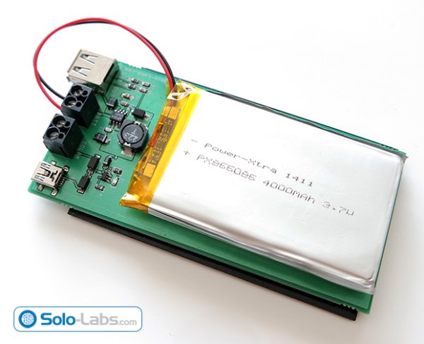
Parts used in the Solar Power Bank:
- Solar panel (3.75V to 6V rated)
- LiPo single-cell battery
- MCP73831 Li-Ion/Li-Po charge management controller
- LT1302-5 step-up (boost) converter
- Mini USB 5V input connector
- USB output connector (5V for gadgets)
- Charge status LED connected to STAT pin
- PCB designed with SoloCapture/SoloPCB tools
- Passive components for charger and boost circuits (resistors, capacitors, inductors as per schematic)
Solar energy is renewable, free, widely available and clean form of energy. It is considered as a serious source of energy for many years because of the vast amounts of energy that is made freely available, if harnessed by modern technology. Many people are familiar with so-called photovoltaic cells, or solar panels, found on things like spacecraft, rooftops, and handheld calculators. The cells are made of semiconductor materials like those found in computer chips. When sunlight hits the cells, it knocks electrons loose from their atoms. As the electrons flow through the cell, they generate electricity.
In this project, we are building a power bank which harvests energy by using a solar panel. The energy gained by the solar panel is stored in a LiPo battery. Then the battery is used to supply a stable 5V which is used by USB gadgets. The power bank can also be charged by an external 5V source. The best thing for this power bank during day that you don’t need to remember to charge it. It charges itself by using the sunlight and you don’t come up with an empty bank.
Circuit Design
The schematic of the project is drawn in SoloCapture, the schematic editor of SoloPCB tools. SoloCapture makes the schematic drawing process very easy and fast. You can download SoloPCB tools at Solo-Labs.com for FREE.
You can download the SoloPCB design files of the project by using the link below.
The circuit consists of two stages. The first stage is the battery charger state based on MCP73831 and the second stage is the step up converter based on LT1302-5 which converts the battery voltage to 5V.
MCP73831 is miniature single-cell, fully integrated Li-Ion, Li-Po charge management controller. Since the input voltage range is 3.75V to 6V, any solar cell rated between these values can be used as the input source. An additional 5V mini USB input is also included in the design which allows you to charge the power bank when sunlight is insufficient. The controller will charge the battery up to 4.2V safely. The led connected to the STAT input off the controller lights up during the entire charge process.
Read more: DIY USB 5V Solar Power Bank
- What is the purpose of this solar power bank?
To harvest solar energy into a LiPo battery and supply a stable 5V for USB gadgets. - Which charge controller is used in the project?
The MCP73831 single-cell Li-Ion/Li-Po charge management controller is used. - What component provides the regulated 5V output?
The LT1302-5 step-up (boost) converter converts the battery voltage to 5V. - What range of solar panel voltages can be used?
Any solar cell rated between 3.75V and 6V can be used as the input source. - Can the power bank be charged without sunlight?
Yes, a mini USB 5V input is included to charge the power bank when sunlight is insufficient. - Up to what voltage does the controller charge the battery?
The controller charges the battery up to 4.2V safely. - How is charging indicated?
An LED connected to the STAT pin lights up during the entire charge process. - Which tool was used to draw the schematic?
The schematic was drawn in SoloCapture, the schematic editor of SoloPCB tools.